Yokogawa EJA115 User Manual
Page 19
IM 01C22K01-01E
2-11
2. HANDLING CAUTIONS
CAUTION
(For TIIS flameproof type without integral indicator)
When the fill fluid near the sensor part moves
from within, the instrument outputs a failure
signal either high or low of the specific signal. In
that case, generate the alarm to identify that the
failure signal is output since the event may
invalidate the flameproof approval.
If the optional integral indicator is equipped, the
indicator identifies the alarm on its display.
Therefore, no other alarm generation is neces-
sary.
Transmitter
Hazardous Location
Nonhazardous Location
Power
Supply
DCS
Display
4 to 20 mA DC
1 to 5 V DC
F0210.EPS
Figure 2.3 Example of using DCS (Distributed Control
System)
CAUTION
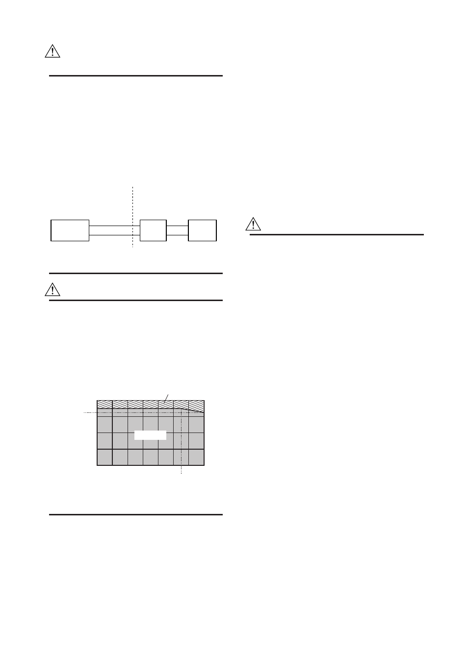
When selecting cables for TIIS flameproof type
transmitters, determine the cables' maximum
allowable heat resistance depending on the
process and ambient temperature condition on
the transmitter as illustrated in Figure 2.4. Use
cables having a maximum allowable heat
resistance of at least 60°C for the transmitter in
Region A and that of 75°C in Region B.
Ambient
Temperature
(
ЊC)
Region B
Process Temperature (
ЊC)
60
40
20
0
Ϫ
20
Ϫ
20
0
20
40
60
80
100
120
50
45
90
F0211.EPS
Region A
Figure 2.4 Selecting Cables
b. TIIS Intrinsically Safe Type
The model EJA Series pressure transmitter with optional
code /JS3, which has obtained certification according to
technical criteria for explosionprotected construction of
electric machinery and equipment (Standards Notifica-
tion No.556 from the Japanese Ministry of Labor) con-
forming to IEC standards, is designed for hazardous ar-
eas where explosive or inflammable gases or vapors
may be present. (This allows installation in Division 0, 1
and 2 areas)
To preserve the safety of flameproof equipment requires
great care during mounting,wiring, and piping. Safety
requirements also place restrictions on maintenance and
repair activities. Users absolutely must read “Installation
and Operating Precautions for TIIS Intrinsically Safe
Equipment” at the end of this manual.
CAUTION
For using a safety-barrier with a pressure
transmitter, the safety-barrier must be certified as
a safety-barrier itself.
A safety-barrier must be used under the follow-
ing condition.
(1) Condition of the current and voltage limits
Maximum output voltage(Uo) ≤ 28V
Maximum output current(Io)
≤ 94.3mA
Maximum output power (Po) ≤ 0.66W
(2) Category and Group
Category
ia
Group
II C
(3) Relations between a maximum allowed
inductance and a field wiring inductance,
between a maximum allowed capacitance
and a field wiring capacitance.
Lo ≥ Li + Lw
Co ≥ Ci + Cw
(Li = 730µH, Ci=11nF)
Lo = Maximum external inductance
Li = Maximum internal inductance
Lw = Field wiring inductance
Go = Maximum external capacitance
Ci = Maximum internal capacitance
Cw = Field wiring capacitance