2 zero point adjustment, Zero point adjustment -2 – Yokogawa EJA115 User Manual
Page 32
IM 01C22K01-01E
7-2
7. OPERATION
NOTE
If any of the error indications above appears on
the display of the integral indicator or BT200,
refer to Subsection 8.5.2 for corrective action.
Verify and Change Transmitter Parameter
Setting and Values
The following parameters are the minimum settings
required for operation. The transmitter has been
shipped with these parameters. To confirm or change
the values, see Subsection 8.3.3.
• Measuring range ................. See Subsection 8.3.3 (2)
• Output/integral indicator mode
............................................ See Subsection 8.3.3 (4)
• Operation mode .................. See Subsection 8.3.3 (9)
7.2 Zero Point Adjustment
Adjust the zero point after operating preparation is
completed. Make sure to close the stop valves on the
upstream and downstream sides before the adjustment.
IMPORTANT
Do not turn off the power to the transmitter
immediately after a zero adjustment. Powering
off within 30 seconds after a zero adjustment will
return the adjustment back to the previous
settings.
The zero point adjustment can be made in either way:
using the zero-adjustment screw of the transmitter or
the BT200 operation.
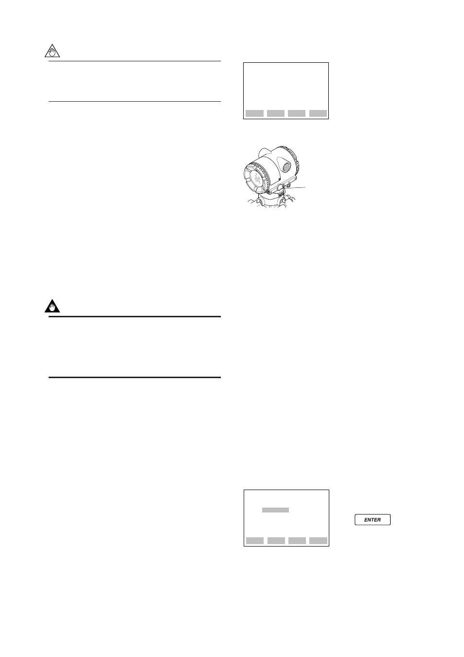
For output signal checking, display the parameter A10:
OUTPUT (%) in the BT200.
Output signal (%)
display
PARAM
A10:OUTPUT(%)
0.0 %
A11:ENGR OUTPUT
A20:AMP TEMP
DATA
DIAG
PRNT
ESC
F0704.EPS
Zero-adjustment
screw
᭹BT200
᭹Zero-adjustment Screw
Using the Transmitter Zero-adjustment
Screw
Before adjusting a screw, check that the parameter
J20: EXT ZERO ADJ displays ENABLE. See
Subsection 8.3.3 (13) for the setting procedure.
Use a slotted screwdriver to turn the zero-adjustment
screw. Turn the screw clockwise to increase the output
or counterclockwise to decrease the output. The zero
point adjustment can be made with a resolution of
0.01% of the setting range. Since the degree of zero
adjustments varies with the screw turning speed, turn
the screw slowly for fine adjustment and quickly for
coarse adjustment.
Using the BT200
Zero point can be adjusted by simple key operation of
the BT200.
Select parameter J10: ZERO ADJ, and press the
ENTER key twice. The zero point will be adjusted
automatically to the output signal 0% (4 mA DC).
Confirm that the setting value displayed for the
parameter is ‘0.0%’ before pressing the ENTER key.
See Subsection 8.3.3 (13) for BT200 operating proce-
dures.
A display when parameter
J10 is selected.
Press key
twice for 0% output 4 mA DC.
SET
J10:ZERO ADJ
–0.0 %
+ 000.0
CLR
ESC
F0705.EPS