Yokogawa EJA115 User Manual
Page 70
IM 01C22K01-01E
10-6
10. GENERAL SPECIFICATIONS
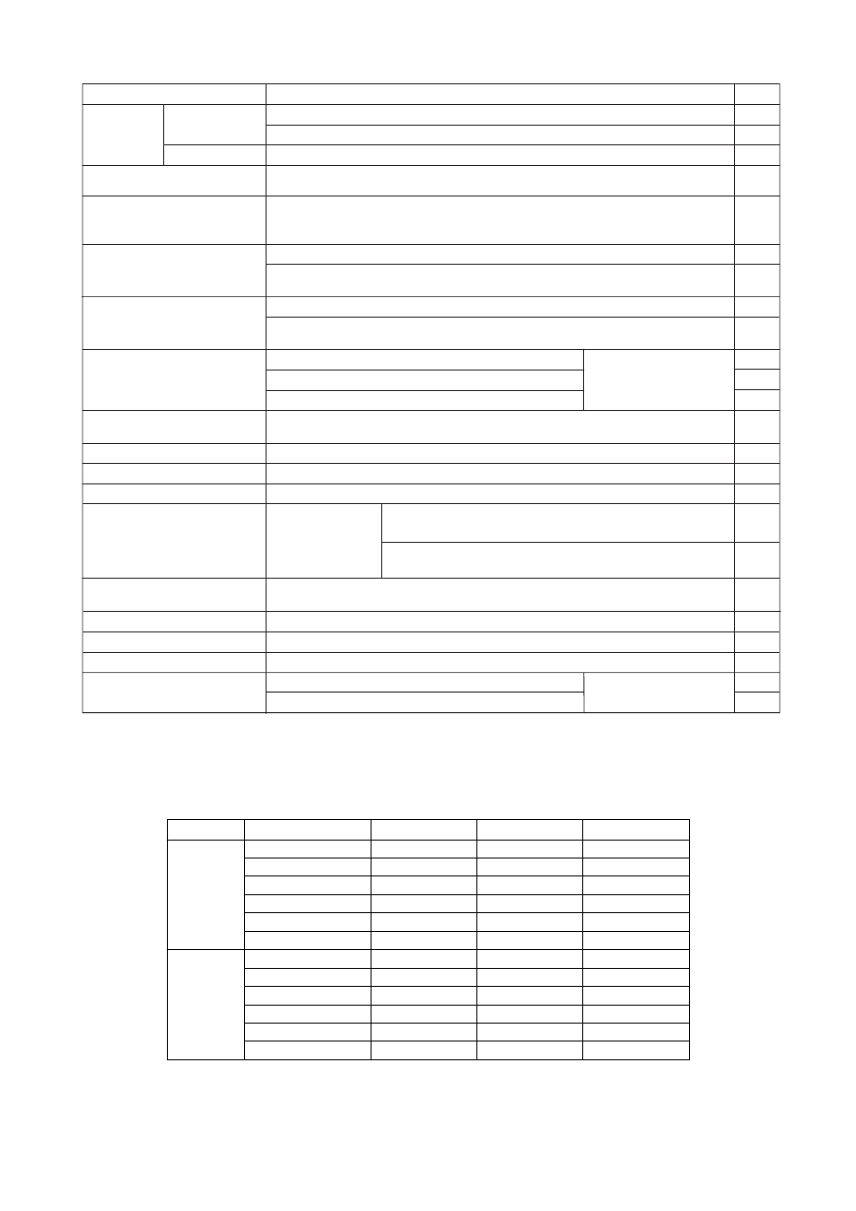
Item
Description
Code
Painting
Color change
Coating change
Lightning protector
Calibration units
Sealing treatment to
SUS630 nuts
Long vent
P
ᮀ
PR
X1
A
K1
D1
D3
D4
Y
U
( See Table for Span and
Range Limits.)
Amplifier cover only
Amplifier cover and terminal cover, Munsell 7.5 R4/14
Epoxy resin-baked coating
Transmitter power supply voltag: 10.5 to 32 V DC (10.5 to 30 V DC for intrinsically safe
type, 9 to 32 V DC for F
OUNDATION
Fieldbus and PROFIBUS PA communication type.)
Allowable current: Max. 6000 A (1
ϫ40 s), Repeating 1000 A (1ϫ40 s) 100 times
316 SST exterior parts
HC
Exterior parts on the amplifier housing (name plates, tag plate, zero-adjustment screw,
stopper screw) will become 316 or 316L SST.
Degrease cleansing treatment
P calibration ( psi unit )
bar calibration ( bar unit )
M calibration (kgf/cm
2
unit )
Sealant ( liquid silicone rubber ) is coated on surfaces of SUS630 nuts used for cover
flange mounting.
Total vent plug Length: 112 mm (standard, 32 mm), Material: SUS316
K2
Degrease cleansing treatment with fluorinated oilfilled capsule.
Operating temperature –20 to 80 °C
Oil-prohibited use
Mill Certificate
Cover flange, Process connector, Manifold, Orifice, and Spacer
Test Pressure: 3.5 MPa{35 kgf/cm
2
}
Test Pressure: 14 MPa{140 kgf/cm
2
}
M12
T01
T02
Pressure test/Leak test Certificate
Nitrogen(N
2
) Gas
Retention time: 10 minutes
K5
Degrease cleansing and dehydrating treatment
K6
Degrease cleansing and dehydrating treatment with fluorinated oilfilled capsule.
Operating temperature –20 to 80 °C
Oil-prohibited use
with dehydrating treatment
Stainless steel amplifier
housing
Amplifier housing material: SCS14A stainless steel
(equivalent to SUS316 cast stainless steel or ASTM CF-8M)
E1
Gold-plate
A1
SUS304 tag plate wired onto transmitter
Stainless steel tag plate
N4
Gold-plated diaphragm
T1006.EPS
Fast response
F1
Update time: 0.125 sec or less, see GS for the response time
Failure alarm down-scale *
1
C1
C2
C3
Output status at CPU failure and hardware error is –5%, 3.2 mA or less.
NAMUR NE43 compliant *
1
Output signal limits:
3.8 mA to 20.5 mA
Failure alarm down-scale: output status at CPU failure and
hardware error is –5%, 3.2 mA or less.
Failure alarm up-scale: output status at CPU failure and
hardware error is 110%, 21.6 mA or more.
* 1:
Applicable for Output signal code D and E. The hardware error indicates faulty amplifier or
capsule. When combining with Optional code F1, output status for down-scale is –2.5%,
3.6 mA DC or less.
Table 1. Measurement Range (Approximate value)
Water
Equivalent
Maximum
Flow Range
l/min
Air
Equivalent
Maximum
Flow Range
Nl/min
Orifice Bore (mm)
L Capsule
M Capsule
H Capsule
0.508
0.864
1.511
2.527
4.039
6.350
0.508
0.864
1.511
2.527
4.039
6.350
0.016 to 0.049
0.046 to 0.145
0.134 to 0.42
0.36 to 1.15
0.92 to 2.9
2.3 to 7.2
0.44 to 1.40
1.30 to 4.10
3.7 to 11.7
10.3 to 32
25 to 79
63 to 198
0.022 to 0.157
0.066 to 0.46
0.19 to 1.35
0.52 to 3.6
1.3 to 9.2
3.3 to 23
0.63 to 4.4
1.85 to 12.9
5.3 to 37
14.6 to 105
36 to 255
89 to 630
0.07 to 0.225
0.21 to 0.67
0.60 to 1.93
1.65 to 5.2
4.1 to 13.0
10 to 33
1.98 to 6.4
5.8 to 18.5
16.7 to 54
47 to 150
113 to 370
280 to 910
T1007.EPS
Note: For details, refer to TI 01C20K00-01E.