5 cleaning and replacing the capsule assembly, Cleaning and replacing the capsule assembly -6 – Yokogawa EJA115 User Manual
Page 62
IM 01C22K01-01E
9-6
9. MAINTENANCE
9.4.5 Cleaning and Replacing the Capsule
Assembly
This subsection describes the procedures for cleaning
and replacing the capsule assembly. (See Figure 9.4.5.)
CAUTION
Cautions for TIIS Flameproof Type Transmit-
ters
Users are prohibited by law from modifying the
construction of a flameproof type transmitter. If
you wish to replace the capsule assembly with
one of a different measurement range, contact
Yokogawa.
The user is permitted, however, to replace a
capsule assembly with another of the same
measurement range. When doing so, be sure to
observe the following.
• The replacement capsule assembly must have
the same part number as the one being re-
placed.
• The section connecting the transmitter and
capsule assembly is a critical element in
preservation of flameproof performance, and
must be checked to verify that it is free of
dents, scratches, and other defects.
• After completing maintenance, be sure to
securely tighten the Allen screws that fasten
the transmitter section and pressure-detector
section together.
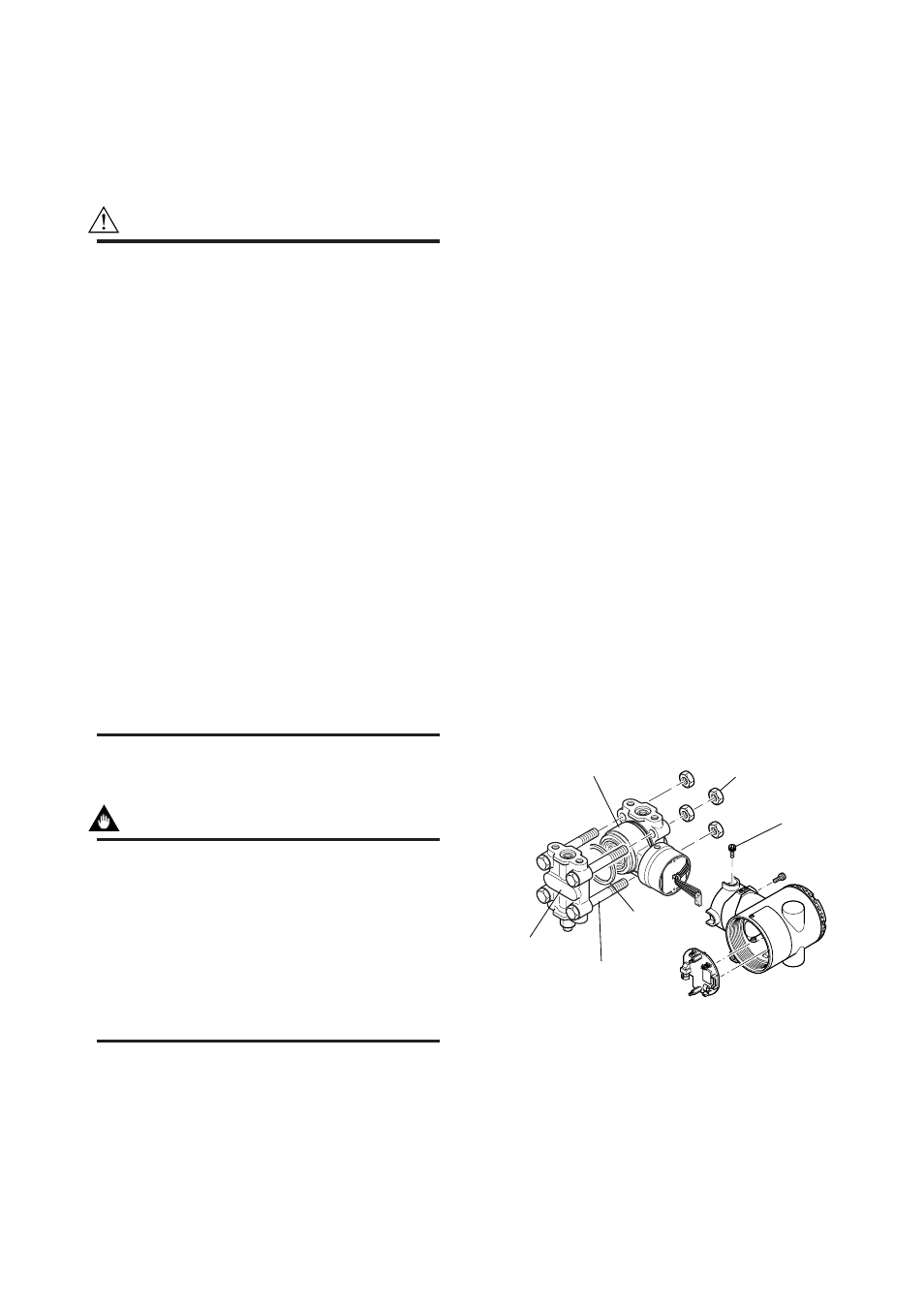
Removing the Capsule Assembly
IMPORTANT
Exercise care as follows when cleaning the
capsule assembly.
• Handle the capsule assembly with care, and be
especially careful not to damage or distort the
diaphragms that contact the process fluid.
• Do not use a chlorinated or acidic solution for
cleaning.
• Rinse thoroughly with clean water and dry
thoroughly after cleaning.
1) Remove the CPU assembly as shown in Subsection
9.4.2.
2) Remove the two Allen screws that connect the
transmitter section and pressure-detector section.
3) Separate the transmitter section and pressure-
detector section.
4) Remove the nuts from the four flange bolts.
5) Hold the capsule assembly by hand and remove the
cover flange.
6) Remove the capsule assembly.
7) Clean the capsule assembly or replace with a new
one.
Reassembling the Capsule Assembly
1) Insert the capsule assembly between the flange
bolts, paying close attention to the relative positions
of the H (high pressure side) and L (low pressure
side) marks on the capsule assembly.
Replace the two capsule gaskets with new gaskets.
2) Install the cover flange on the high pressure side,
and use a torque wrench to tighten the four nuts
uniformly to a torque of 39 N·m {4 kgf·m}.
3) After the pressure-detector section has been reas-
sembled, a leak test must be performed to verify
that there are no pressure leaks.
4) Reattach the transmitter section to the pressure-
detector section.
5) Tighten the two Allen screws. (Tighten the screws
to a torque of 5 N·m)
6) Install the CPU assembly according to Subsection
9.4.2.
7) After completing reassembly, adjust the zero point
and recheck the parameters.
F0906.EPS
Cover flange
Capsule assembly
Capsule
gasket
Flange bolt
Allen screw
Nut
Figure 9.4.5 Removing and Mounting the Pressure-
detector Section