Yokogawa EJA110A User Manual
Page 74
IM 01C21B01-01E
10-10
10. GENERAL SPECIFICATIONS
᭹
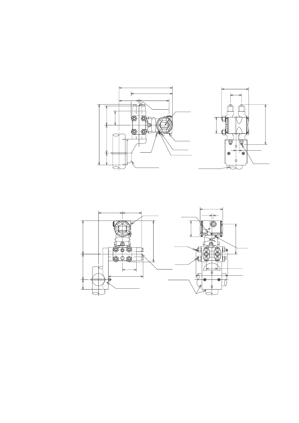
Model EJA130A
Vertical Impulse Piping Type
Process connector upside (INSTALLATION CODE ‘6’) (For CODE ‘2’, ‘3’ or ‘7’,
refer to the notes below.)
Unit: mm (approx. inch)
Low
pressure
side (Note 1)
High
pressure
side
Terminal
side
Internal
indicator
(Optional)
Mounting bracket
(L-type)
Vent plug
Drain plug
2B pipe(ø60.5)
Ground
terminal
Process
connection
Zero
adjustment
Conduit
connection
53(2.09)
124(4.88)
279(10.98)
68(2.68)
94(3.70)
97(3.82)
146(5.75)
200(7.87)
259(10.20)
ø78
(3.07)
132(5.20)
192(7.56)
54
(2.13)
9
(note3)
(0.35)
F1004.EPS
Shrouding bolt
(Note 4)
Horizontal Impulse Piping Type
(INSTALLATION CODE ‘9’) (For CODE ‘8’, refer to the notes below)
154(6.06)
54(2.13)
9
(note3)
(0.35)
110(4.33)
ø78
(3.07)
146(5.75)
116(4.57)
94(3.70)
169(6.65)
124(4.88)
162(6.38)
68(2.68)
200(7.87)
47
(1.85)
Drain plug
2B pipe(Ø60.5)
Ground
terminal
Zero
adjustment
Vent plug
Mounting bracket
(Flat-type)
Conduit
connection
Process
connection
Low
pressure
side (Note 1)
High
pressure
side
F1005.EPS
Note 1: When INSTALLATION CODE ‘2’, ‘3’ or ‘8’ is selected, high and low pressure side on above
figure are reversed.
(i. e. High pressure side is on the right side.)
Note 2: When INSTALLATION CODE ‘3’ or ‘7’ is selected, process connection and mounting bracket on
above figure are reversed.
Note 3: 9 mm (0.35 inch) for right side high pressure type. (CODE ‘2’, ‘3’ or ‘8’).
Note 4: Applicable only for ATEX and IECEx Flameproof type.