Installing impulse piping, 1 impulse piping installation precautions, 1 connecting impulse piping to the transmitter – Yokogawa EJA110A User Manual
Page 26: Installing impulse piping -1, Impulse piping installation precautions -1, Connecting impulse piping to the transmitter -1
IM 01C21B01-01E
5-1
5. INSTALLING IMPULSE PIPING
5.
INSTALLING IMPULSE PIPING
5.1 Impulse Piping Installation
Precautions
The impulse piping that connects the process outputs to
the transmitter must convey the process pressure
accurately. If, for example, gas collects in a liquid-
filled impulse piping, or the drain of a gas-filled
impulse piping becomes plugged, the impulse piping
will not convey the pressure accurately. Since this will
cause errors in the measurement output, select the
proper piping method for the process fluid (gas, liquid,
or steam). Pay careful attention to the following points
when routing the impulse piping and connecting the
impulse piping to the transmitter.
5.1.1 Connecting Impulse Piping to the
Transmitter
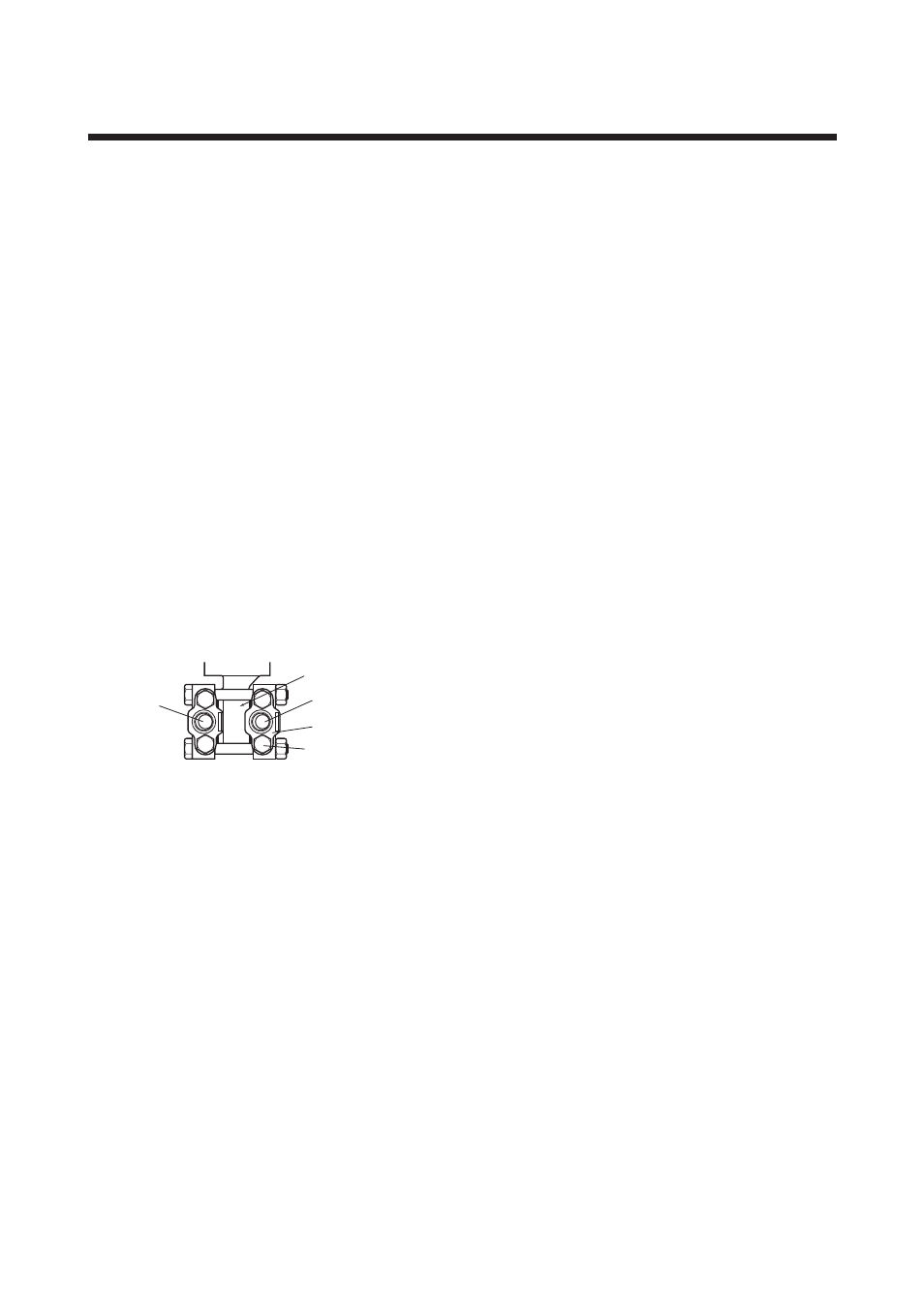
(1) Check the High and Low Pressure Connec-
tions on the Transmitter (Figure 5.1.1a)
Symbols “H” and “L” are shown on a capsule assem-
bly to indicate high and low pressure side. Connect the
impulse piping to the “H” side, and the low impulse
piping to the “L” side.
F0501.EPS
Pressure
connection
“H” and “L” are shown
Process connection
Process connector
Bolt
Figure 5.1.1a “H” and “L” Symbols on a Capsule
Assembly
(2) Changing the Process Connector Piping
Connections (Figure 4.1)
The impulse piping connection distances can be
changed between 51 mm, 54 mm and 57 mm by
changing the orientation of the process connectors.
This is convenient for aligning the impulse piping with
the process connectors when connecting the piping.
(3) Tightening the Process Connector Mount-
ing Bolts
After connecting the impulse piping, tighten the
process connector mounting bolts uniformly.
(4) Connecting the Transmitter and 3-Valve
Manifold
A 3-valve manifold consists of two stop valves to
block process pressure and an equalizing valve to
equalize the pressures on the high and low pressure
sides of the transmitter. Such a manifold makes it
easier to disconnect the transmitter from the impulse
piping, and is convenient when adjusting the transmit-
ter zero point.
There are two types of 3-valve manifold: the pipe-
mounting type and the direct-mounting type; care
should be taken with respect to the following points
when connecting the manifold to the transmitter.
Pipe-Mounting Type 3-Valve Manifold
(Figure 5.1.1b)
1) Screw nipples into the connection ports on the
transmitter side of the 3-valve manifold, and into the
impulse piping connecting ports on the process
connectors. (To maintain proper sealing, wind
sealing tape around the nipple threads.)
2) Mount the 3-valve manifold on the 50 mm (2-inch)
pipe by fastening a U-bolt to its mounting bracket.
Tighten the U-bolt nuts only lightly at this time.
3) Install the pipe assemblies between the 3-valve
manifold and the process connectors and lightly
tighten the ball head lock nuts. (The ball-shaped
ends of the pipes must be handled carefully, since
they will not seal properly if the ball surface is
scratched or otherwise damaged.)
4) Now tighten the nuts and bolts securely in the
following sequence:
Process connector bolts
→
transmitter-end ball head
lock nuts
→
3-valve manifold ball head lock nuts
→
3-valve manifold mounting bracket U-bolt nuts