2) checking with integral indicator, Checking with integral indicator -21, Error messages — dpharp integral indicator – Yokogawa EJA115 User Manual
Page 28
IM 01C22T01-01E
2-21
2. HART COMMUNICATOR OPERATION
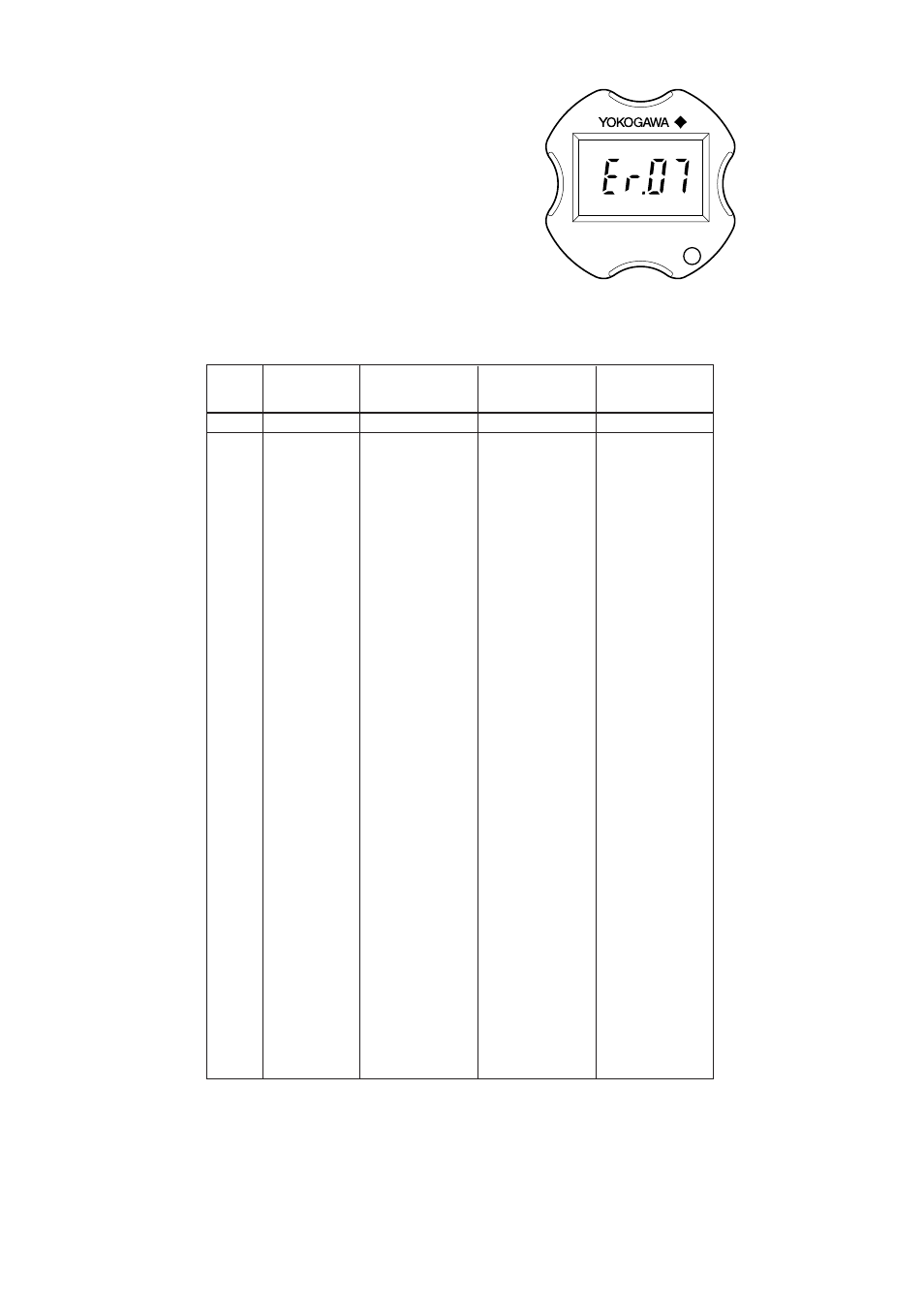
(2) Checking with Integral Indicator
If an error is detected in the self-diagnostic, an error
number is displayed on the integral indicator. If there is
more than one error, the error number changes at two-
second intervals.
See Table 2.4.1 regarding the error numbers.
F0243.EPS
Figure 2.4.1 Identifying Problems Using the Integral
Indicator
• Error Messages — DPharp Integral Indicator
Integral
Indicator
Display
Description
Cause
Countermeasure
Output Operation
during Error
None
----
GOOD
ERROR
Er. 01
CAP MODULE
FAULT
Er. 02
AMP MODULE
FAULT
Er. 03
OUT OF RANGE
Er. 04
OUT OF SP
RANGE
Er. 05
OVER TEMP
(CAP)
Er. 06
OVER TEMP
(AMP)
Er. 07
OVER OUTPUT
Er. 08
OVER DISPLAY
Er. 09
ILLEGAL LRV
Er. 10
ILLEGAL URV
Er. 11
ILLEGAL SPAN
Er. 12
ZERO ADJ OVER
Static pressure
exceeds specified
range.
Capsule temperature
is outside range
(–50 to 130
°
C).
Amplifier temperature
is outside range
(–50 to 95
°
C).
Output is outside high
or low range limit
value.
Displayed value is
outside high or low
range limit value.
LRV is outside setting
range.
URV is outside setting
range.
SPAN is outside
setting range.
Zero adjustment is too
large.
T0206.EPS
Capsule problem
Amplifier problem
Input is outside
measurement range
limit of capsule.
Displays present
output.
Displays present
output.
Displays present
output.
Outputs high or low
range limit value.
Displays high or low
range limit value.
Holds output
immediately before
error occurrence.
Holds output
immediately before
error occurrence.
Holds output
immediately before
error occurrence.
Displays present
output.
Outputs the signal
according to status of
burnout direction
switch (High or Low).
Outputs the signal
according to status of
burnout direction
switch (High or Low).
Outputs high range
limit value or low
range limit value.
Check line pressure
(static pressure).
Use heat insulation or
make lagging to keep
temperature within
range.
Use heat insulation or
make lagging to keep
temperature within
range.
Check input and range
setting, and change
them as needed.
Check input and
display conditions and
modify them as
needed.
Check LRV and
modify as needed.
Check URV and
modify as needed.
Check SPAN and
change as needed.
Readjust zero point.
Replace capsule
when error keeps
appearing even after
resart.*
1
Replace amplifier.
Check input.
Integral
Indicator
Display
Description
Cause
Countermeasure
Output Operation
during Error
None
----
GOOD
ERROR
Er. 01
CAP MODULE
FAULT
Er. 02
AMP MODULE
FAULT
Er. 03
OUT OF RANGE
Er. 04
OUT OF SP
RANGE
Er. 05
OVER TEMP
(CAP)
Er. 06
OVER TEMP
(AMP)
Er. 07
OVER OUTPUT
Er. 08
OVER DISPLAY
Er. 09
ILLEGAL LRV
Er. 10
ILLEGAL URV
Er. 11
ILLEGAL SPAN
Er. 12
ZERO ADJ OVER
Static pressure
exceeds specified
range.
Capsule temperature
is outside range
(–50 to 130
°
C).
Amplifier temperature
is outside range
(–50 to 95
°
C).
Output is outside high
or low range limit
value.
Displayed value is
outside high or low
range limit value.
LRV is outside setting
range.
URV is outside setting
range.
SPAN is outside
setting range.
Zero adjustment is too
large.
Capsule problem*
1
Amplifier problem
Input is outside
measurement range
limit of capsule.
Displays present
output.
Displays present
output.
Displays present
output.
Outputs high or low
range limit value.
Displays high or low
range limit value.
Holds output
immediately before
error occurrence.
Holds output
immediately before
error occurrence.
Holds output
immediately before
error occurrence.
Displays present
output.
Outputs the signal
according to status of
burnout direction
switch (High or Low).
Outputs the signal
according to status of
burnout direction
switch (High or Low).
Outputs high range
limit value or low
range limit value.
Check line pressure
(static pressure).
Use heat insulation or
make lagging to keep
temperature within
range.
Use heat insulation or
make lagging to keep
temperature within
range.
Check input and range
setting, and change
them as needed.
Check input and
display conditions and
modify them as
needed.
Check LRV and
modify as needed.
Check URV and
modify as needed.
Check SPAN and
change as needed.
Readjust zero point.
Replace capsu
Replace amplifier.
Check input.
*1 : This error code appears at capsule problem or when an illiegal overpressure is applied to the
pressure sensor.
*2 : If the normal pressure is regained, the Er.01 will disappear according to the setting of the parameter
of Auto recover. When the Auto recover is set to ON(default setting), the Er.01 will disappear auto-
matically. When the Auto recover is set to OFF, restart the transmitter to cancel Er.01. If no error
code appears then, perform necessary adjustments such as zero-adjustment to continue the
operation. If the error code still appears. replace the capsule assembly.