13) sensor trim, 13) test output -13 (14) sensor trim -13 – Yokogawa EJA115 User Manual
Page 20
IM 01C22T01-01E
2-13
2. HART COMMUNICATOR OPERATION
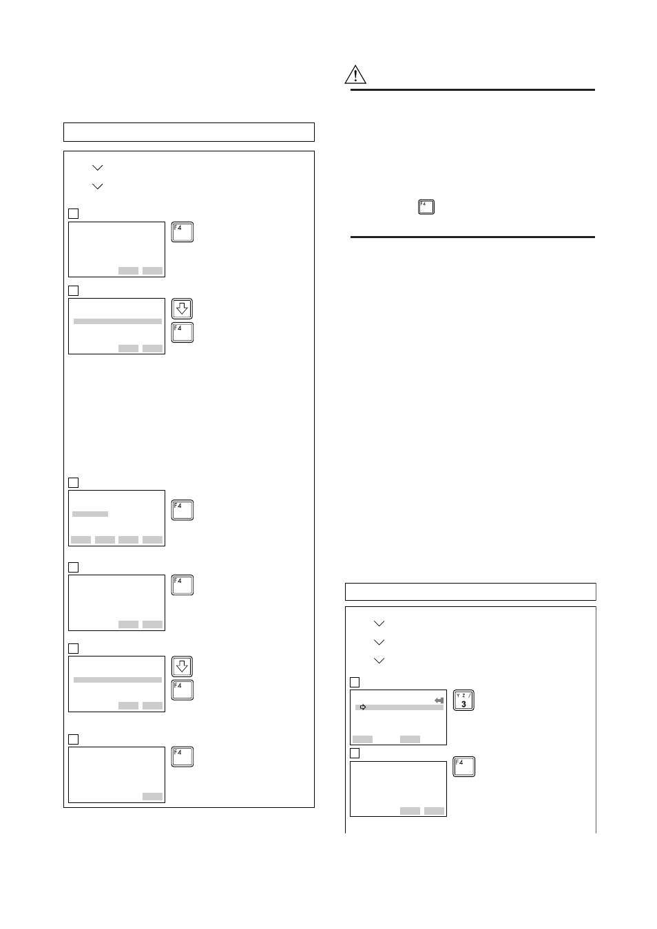
(13) Test Output
This feature can be used to output a fixed current from
3.2 mA (–5%) to 21.6 mA (110%) for loop checks.
1
F0227.EPS
Set the control loop in manual
mode, and press OK (F4).
EJA:
WARN-loop should be
removed from
automatic control
DEL
SET
ABORT
OK
EJA:
Choose analog output
level
1 4mA
2 20mA
3 Other
4 End
DEL
SET
ABORT
ENTER
2
Select Other, and press ENTER
(F4).
Supplementary explanation.
1. 4 mA:
Outputs a 4 mA current signal
2. 20 mA:
Outputs a 20 mA current signal
3. Other:
Sets a desired output using the
alphanumeric keys
4. End: Exits
EJA:
Output
4.000
HELP
DEL
ABORT
ENTER
3
Enter 12, and press ENTER (F4).
A fixed current of 12 mA is output.
EJA:
Fld dev output is
fixed at 12.000 mA
DEL
ABORT
4
Press OK (F4).
HELP
SEND
OK
×
2
(ENTER)
×
3
(ENTER)
(ENTER)
(OK)
(OK)
‘1 2’
(OK)
EJA:
Choose analog output
level
1 4mA
2 20mA
3 Other
4 End
DEL
ABORT
5
To finish the loop test, select End,
and press ENTER (F4).
HELP
SEND
ENTER
EJA:
NOTE-loop may be
returned to automatic
control
DEL
ESC
6
Press OK (F4).
HELP
SEND
OK
Example: To output 12 mA (50%)
1. Device setup
2. Diag/Service
2. Loop test
CAUTION
1. Test output is held for approximately 10
minutes, and then released automatically
after the time has elapsed. Even if the HART
Communicator power supply is turned off or
the communication cable is disconnected
during test output, it is held for approximately
10 minutes.
2. Press the
(OK) key to release test output
immediately.
(14) Sensor Trim
Each DPharp EJA Series Transmitter is factory
characterized. Factory characterization is the process of
comparing a known pressure input with the output of
each transmitter sensor module over the entire pressure
and temperature operating range. During the character-
ization process, this comparison information is stored
in the transmitter EEPROM. In operation, the transmit-
ter uses this factory-stored curve to produce a process
variable output (PV), in engineering units, dependent
on the pressure input. The sensor trim calibration
procedure allows you to make corrections to the
calculated process variable.
There are two ways to trim the sensor: full sensor trim
and zero trim. A full sensor trim is a two point process,
in which two accurate end-point pressures are applied
(equal to or greater than the range values), and all
output is linearized between them. A zero trim is a
one-point adjustment typically used to compensate for
mounting position effects or zero shifts caused by static
pressure. (See section 1.1.1)
1
F02281.EPS
Select the Lower Sensor trim.
EJA:
Sensor trim
1 Zero trim
2 Pres
3 Lower sensor trim
4 Upper sensor trim
5 Sensor trim points
HELP
SET
HOME
OK
EJA:
Apply low pressure
DEL
SET
ABORT
OK
2
Apply a standard pressure of 1000
mmH
2
O to the transmitter. After
obtaining a stable pressure, press
OK (F4).
(OK)
Example 1: For the range of 1000 to 3000 mmH
2
O
1. Device setup
2. Diag/Service
3. Calibration
3. Sensor Trim