7) bi-directional flow measurement, 8) integral indicator display mode, 9) integral indicator scale – Yokogawa EJA115 User Manual
Page 17: Bi-directional flow measurement -10, Change output limits -10, Integral indicator display mode -10
IM 01C22T01-01E
2-10
2. HART COMMUNICATOR OPERATION
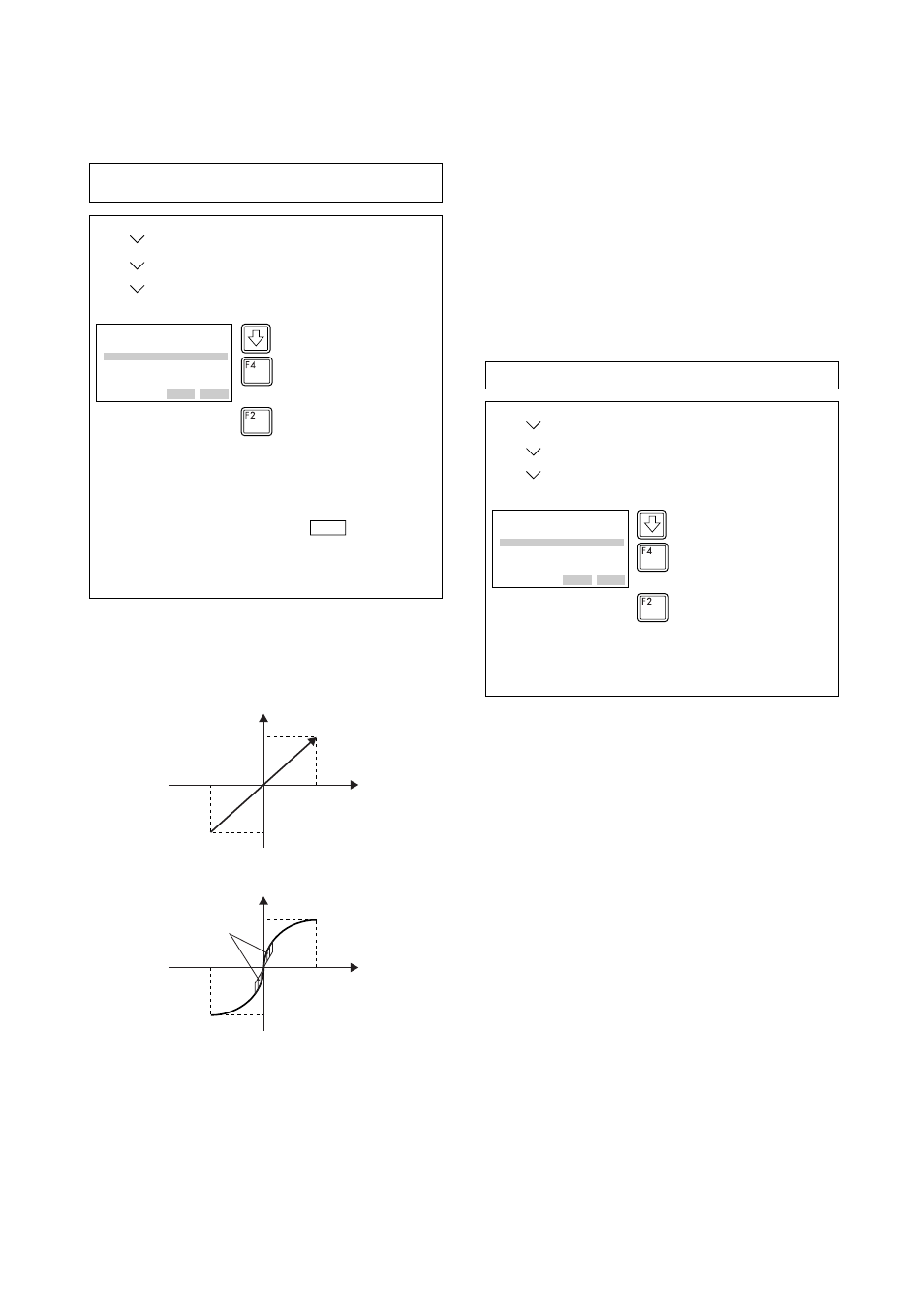
(7) Bi-directional Flow Measurement
(a)
Bi-dir mode
enables selection of 50% output at an
input of 0 mmH
2
O.
F0218.EPS
(ENTER)
EJA:
Bi-dir mode
OFF
off
on
HELP
SEND
ESC
ENTER
Call up the Bi-dir mode Display
Select on, and press ENTER (F4).
Press SEND (F2) to send the data
to the transmitter, then check to
confirm that disappears.
(SEND)
1. Device setup
4. Detailed setup
2. Signal condition
8. Bi-dir mode
SEND
Note: The measurement range changes to –3000 to 0 to
3000mmH
2
O (output 0% to 50% to 100%).
Note that LRV and URV are not changed.
Example: If measurement range is 0 to 3000mmH
2
O
(LRV = 0 mmH
2
O, URV = 3000 mmH
2
O)
(b) Combining
Bi-dir mode
with
Xfer fnctn
provides
a square root output computed independently for
0% to 50% output and for 50% to 100% output.
20 mA (100% display)
4 mA (–100% display)
Output mode “LINEAR”
LRV
HRV
F0219.EPS
20 mA (100% display)
Low Cut
4 mA (–100% display)
Output mode “SQUARE ROOT”
LRV
HRV
(8) Change Output Limits
The range of normal ouput is preset at factory from
Ϫ5.0 to 110.0% unless otherwise specified or condi-
tioned, and the output is limited with these upper and
lower values. This output range can be changed, for
example, to meet the requirements of NAMUR, within
the settable range. Set the lower limit with
AO lower
limit %
and upper limit with
AO Upper Limit %
.
Settable range :
Ϫ5.0 to 110.0 (%),
Upper limit > Lower limit
(9) Integral Indicator Display Mode
F0220.EPS
(ENTER)
EJA:
Display fnctn
Linear
Linear
Square Root
HELP
SEND
ESC
ENTER
Select Square Root and press
ENTER (F4).
Press SEND (F2) to send data.
(SEND)
1. Device setup
4. Detailed setup
4. Display condition
2. Display fnctn
Example: Change from Linear to Sq root