Maple Systems OIT4160B User Manual
Page 8
2.2. Power Supply Selection
• The power supply used to power the OIT should have an output between +12
and +30 VDC, meeting Class 2 power requirements. The voltage should
measure between +12 and +30V at the OIT between Pins 1 and 2 of the power
connector. A 24 VDC, 1.2 amp linear power supply dedicated to the OIT is
recommended.
• The power cable for the OIT should be 18AWG 2-conductor stranded wire with
a shield wire and protective shield (foil or braid). The shield of the OIT power
cable must be connected to earth ground at both ends of the cable. Please refer to
the “Connect OIT to Power” section for more information.
• A power line filter installed at the AC input to the OIT power supply is highly
recommended as a safeguard against conducted RF noise, which is often present
on factory power lines. The wires connecting the output of the power line filter
to the power supply should be kept as short as possible to minimize any
additional noise pickup. The case of the power line filter should be connected to
a quiet earth ground. The power line filter should have a current rating of at least
three amps with common mode and differential mode attenuation.
• The power supply that provides power to the OIT should not be used to power
switching relays or solenoids unless noise filter caps are connected to each relay.
2.3. OIT Cable Routing
• Input and output (I/O) wiring must be in accordance with Class I, Division 2
wiring methods and in accordance with the authority having jurisdiction.
• Always route the OIT communication cable and power cable away from any AC
voltage or PLC/host control wires.
• Never bundle the OIT cables together with 120 VAC power wires or with relay
wiring.
• Try to keep at least 8 inches (20 cm) of separation between the OIT cables and
other power wiring. If voltages greater than 120 VAC are used in the system,
greater separation is required.
• If the OIT cables must come near AC wiring, make sure they cross at 90 degrees.
• Running AC power wires in a separate grounded conduit is the preferred method
for electrical noise reduction.
1010-0105, REV 03
8
OIT3160B/4160B
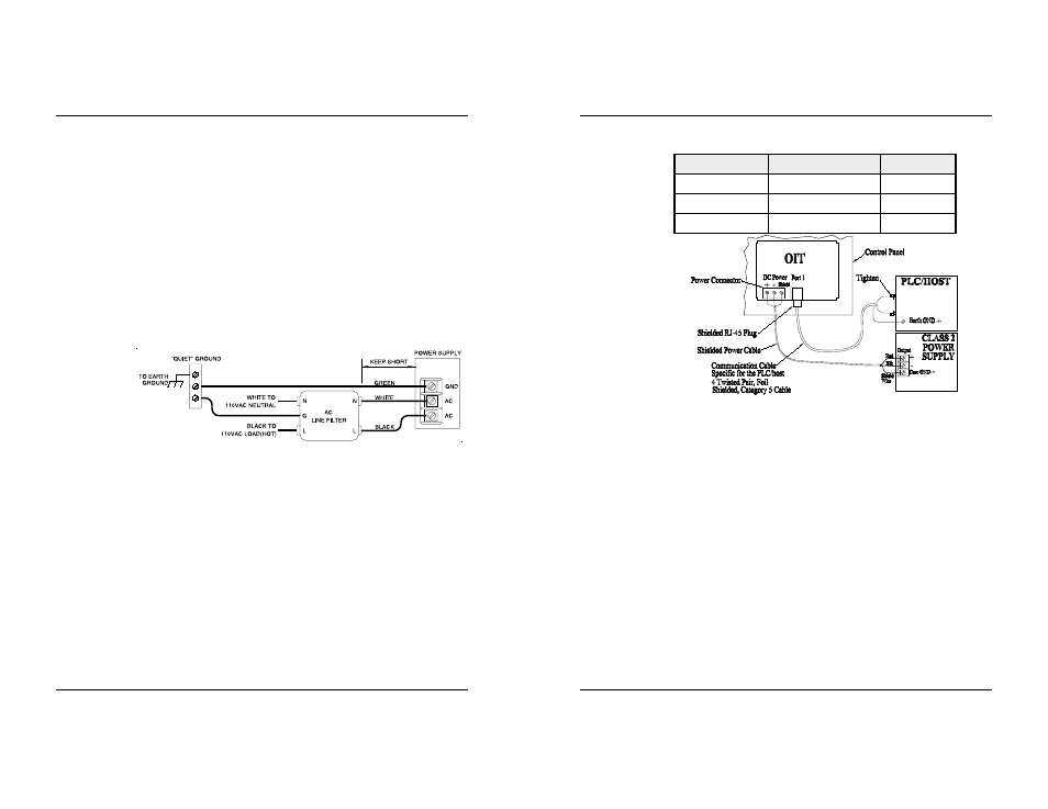
Figure 2 Power Line Filter Connection
2. Install the wires into the Class 2 power supply as follows (colors shown are
for Maple Systems Cable P/N 6030-0009):
COLOR
POWER SUPPLY
OIT
Red
+ Output
(+)
Black
- Output
(-)
Shield Wire
Case Ground
Shield
NOTE: The power connector on the OIT has M3 slotted screws.
3.5. Connect OIT to PLC/Host
Each PLC/host supported by Maple Systems has its own wiring requirements.
Maple Systems offers pre-constructed OIT-to-PLC communication cables for
most PLCs. Most cables are available for same day shipment from Maple Systems.
They are built and tested for high reliability and are strongly recommended. Maple
Systems also builds custom cables—contact the factory for information.
Components and instructions necessary to construct your own OIT-to-PLC
communications cables are also available. Refer to Maple Systems’ Price List or
web site (www.maple-systems.com).
NOTE: Refer to the ASCII Slave Protocol Guide or the STEP1 Protocol Operation
Manual for information on constructing OIT-to-ASCII host communication
cables.
STEPS
1. Connect the RJ-45 plug end of the communication cable into the serial port
on the OIT.
2. Ensure that the locking tab has secured the plug.
1010-0105, REV 03
INSTALLATION MANUAL
13
Figure 5 OIT3160/4160 PLC Connection