Safety warnings, Oit configuration wiring, Hazardous locations – Maple Systems OIT4160B User Manual
Page 6: Connect oit to pc for configuration
1. Safety Warnings
WARNING Hazardous location environment. This unit is suitable
for use in Class I, Division 2 groups A, B, C and D or Non-Hazardous
locations only.
WARNING All input and output (I/O) wiring must be in accordance
with Class I, Division 2 wiring methods and in accordance with the
authority having jurisdiction.
WARNING Explosion hazard. Do not disconnect equipment unless
power has been switched off or the area is known to be non-hazardous.
WARNING Explosion hazard. Do not connect more than one main
power supply to any one fuse or circuit breaker.
WARNING Explosion hazard. Substitution of components may
impair suitability for Class I, Division 2.
1.1. Hazardous Locations
Install the MicroOIT terminal using publication NFPA 70E, Electrical Safety
Requirements for Employee Workplaces as a guide. Be certain to follow all
directions for installing and connecting DC power to the MicroOIT.
When used in a hazardous environment, the ultimate enclosure must be in
accordance with Class I, Division 2 wiring methods as described in the National
Electrical Code (ANSI/NFPA 70).
All peripheral equipment must be suitable for the location in which it is used.
Use only a Class 2 power source as described in the National Electrical Code
(ANSI/NFPA 70).
WARNING Use only with Class 2 power source limited to 30 VDC
open circuit and 8A short circuit.
1010-0105, REV 03
6
OIT3160B/4160B
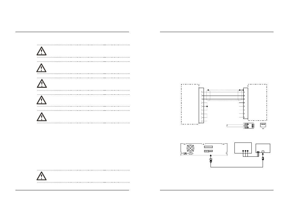
4. OIT Configuration Wiring
The OIT3160 and OIT4160 must be configured for a particular protocol before use.
The OITware-200 or STEPware-100 software (used on a computer with Windows
3.1 or later) is used for OIT configuration. For detailed instructions on installing
and using the software, please refer to the software documentation.
4.1. Connect OIT to PC for Configuration
To configure the OIT using Maple Systems’ configuration software, remove the
PLC/host cable from the serial port on the OIT and connect the OIT to the computer
using an RS-232 serial communications cable (P/N 7431-0096, purchased
separately from Maple Systems). The configuration cable should be connected to
the proper COM port on your computer, then attached to the serial port on the OIT.
See Figure 7 below for serial port pin assignments.
INSTALLATION MANUAL
15
1010-0105, REV 03
CTS
DSR
RTS
DCD
DTR
8
7
6
4
1
RXD
TXD
6
5
RJ-45
OIT
PC
4 Return
Ground 5
TXD 3
RXD 2
9S
1 TXD+
2 TXD-
3 CTS
7 RXD-
8 RXD+
N/C
N/C
N/C
N/C
N/C
9
N/C
Top
8
1
8
1
Pin Configuration
RJ-45 Plug
Printer
Com2
Back
of
OIT
7431-0096
Com1
OIT
PC
OIT Power Supply
Power
Maple Systems
OIT to PC cable
(If mouse is using
Com 1, use Com2)
Figure 7 OIT3160/4160 to PC RS-232 Communication