Maple Systems Windows Embedded CE 6.0 Pro Edition User Manual
Page 9
1010-1017 Rev. 00
9
To connect the OMI to power:
1. Connect the power cable to the OMI.
a. Strip the power cable shield to expose 2” of the black and
red wires.
b. Strip about ¼” of insulation from the black and red wires.
c. Connect the red wire to the 24V DC positive (+) input of the
OMI power terminal block.
d. Connect the black wire to the 24V DC negative (–) input of
the OMI power terminal block.
e. Connect the power cable shield wire to the OMI power
terminal block’s chassis ground input.
2. Route the power cable to the OMI power supply. The power
cable should not be any longer than necessary.
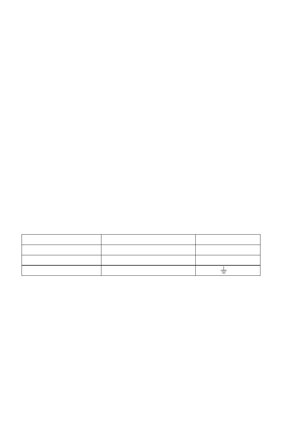
3. Install the power supply wires as follows (with colors shown for
Maple Systems cable P/N 6030-0009):
Color
Power Supply
OMI
Red
+Output/+24V DC
+24 V
Black
–Output/+24V DC return
GND
Shield
Case ground
FG or
NOTE: The power connector on the OMI5000 Series uses a 3-position
terminal block with screw-down clamps. Lugs are not required.
Panel Preparation
A metal panel or mounting surface with a minimum thickness of 15
gauge (0.059 in/3.3 mm) if cold-rolled steel or hardened steel, or 10
gauge (0.101 in/2.6 mm) if aluminum alloy (6061-T6 preferred) is
required. Thinner panels or surfaces may bow between the mounting
clamps and not form a seal with the gasket. Make sure all supplied
mounting clamps are used and that the panel does not flex or bow more
than 0.010 in. to ensure a proper seal.