Maple Systems Windows Embedded CE 6.0 Pro Edition User Manual
Page 7
1010-1017 Rev. 00
7
and differential mode attenuation. In applications that may have high
frequency noise present, we also recommend using a resistor (~1 MΩ)
and capacitor (~4700 pF) in parallel to clean earth ground on the DC
output of the power supply.
Do not use the power supply used to provide power to the OMI to power
switching relays, solenoids, or other active devices.
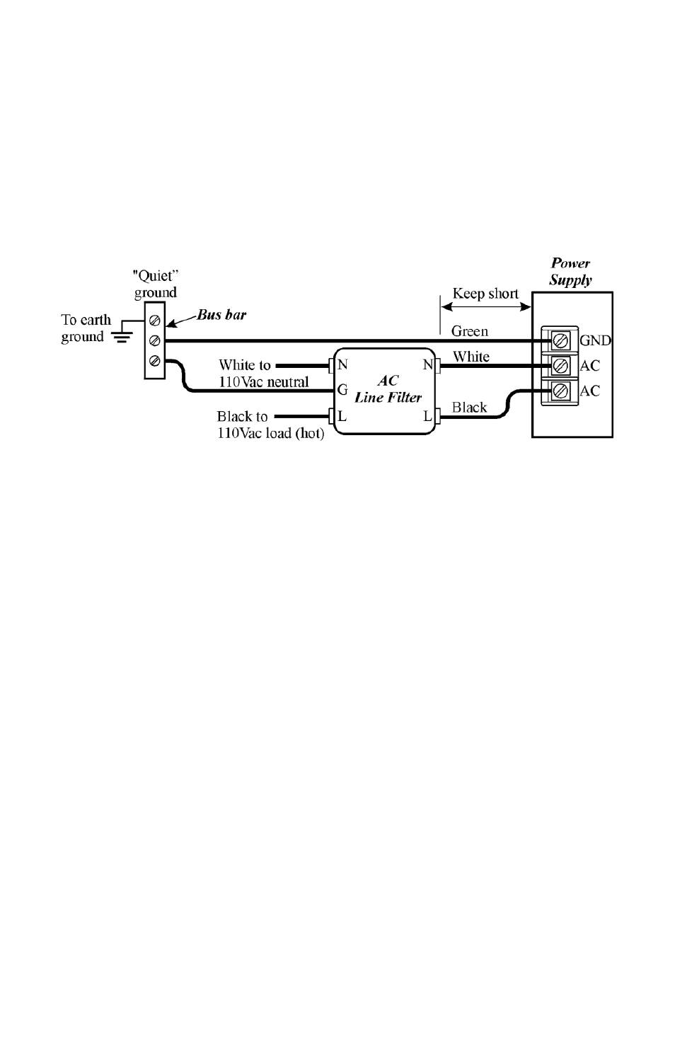
Figure 3: Power Line Filter Connection
Cable Routing and Noise Immunity
Follow these guidelines when routing cables to the OMI:
Always route the OMI communication cable and the power cable
away from any AC voltage or rapidly switching DC control
lines.
Never bundle the OMI cables together with 120VAC power
wires or with relay wiring.
Try to keep at least 8 inches (20 cm) of separation between the
OMI cables and other power wiring. If voltages greater than
120VAC are used in the system, greater separation is required.
If the OMI cables must come near AC wiring, make sure they
cross at 90 degrees.
Run AC power wires in a separate grounded conduit to reduce
electrical noise interference.
Keep the cable lengths for the OMI as short as possible. Do not
coil excess cable and place it next to AC powered equipment.
Cover any equipment used in the enclosure that operates at high
frequency or high current levels with a grounded metal shield.