Maple Systems Windows Embedded CE 6.0 Pro Edition User Manual
Page 6
1010-1017 Rev. 00
6
Technical Note #1027, “OIT Ground Wiring and Electrical Noise
Reduction,” which you can find in the Support Center Technical Notes
section on our web site.
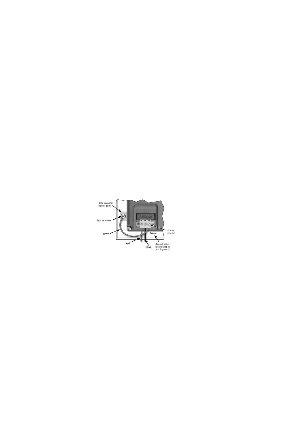
Connect OMI Chassis Ground to Control Panel
To reduce the possibility of electrical interference, connect the chassis
ground terminal of the OMI to a clean earth ground. If the control panel
is metal, make sure it is properly grounded. Then connect a short heavy-
gauge wire (#14 AWG) from the chassis ground terminal of the OMI to a
mounting bolt on the control panel door. The mounting bolt must have
good electrical contact to the control panel; scrape away any paint that
may be covering the panel to provide a good connection.
NOTE: If the control panel is made of a non-conductive material, it is
essential that you connect the chassis ground terminal of the OMI to a
clean earth ground point located close to the panel.
Figure 2: Chassis Ground Connection
Power Supply Selection
The power supply used to power the OMI should provide an output of
+24 VDC ±20% measured at the HMI power terminal block. A 24VDC
regulated power supply dedicated to the OMI is recommended. Use a
power supply with adequate current rating based upon your particular
model (visit the Support Center Specifications page on our website).
A power line filter installed at the AC input to the OMI power supply is
highly recommended as a safeguard against conducted RF noise, which
is often present on factory power lines. The wires connecting the output
of the power line filter to the power supply should be kept as short as
possible to minimize any additional noise pickup. The case of the power
line filter should be connected to a quiet earth ground. The power line
filter should have a current rating of at least 3 Amps with common mode