Overview of dm, Series e double valve function – Ross Controls CATEGORY 4 - 3_2 VALVES SERIES DM2 C, E User Manual
Page 3
Overview of DM
1
Series E Double Valve Function
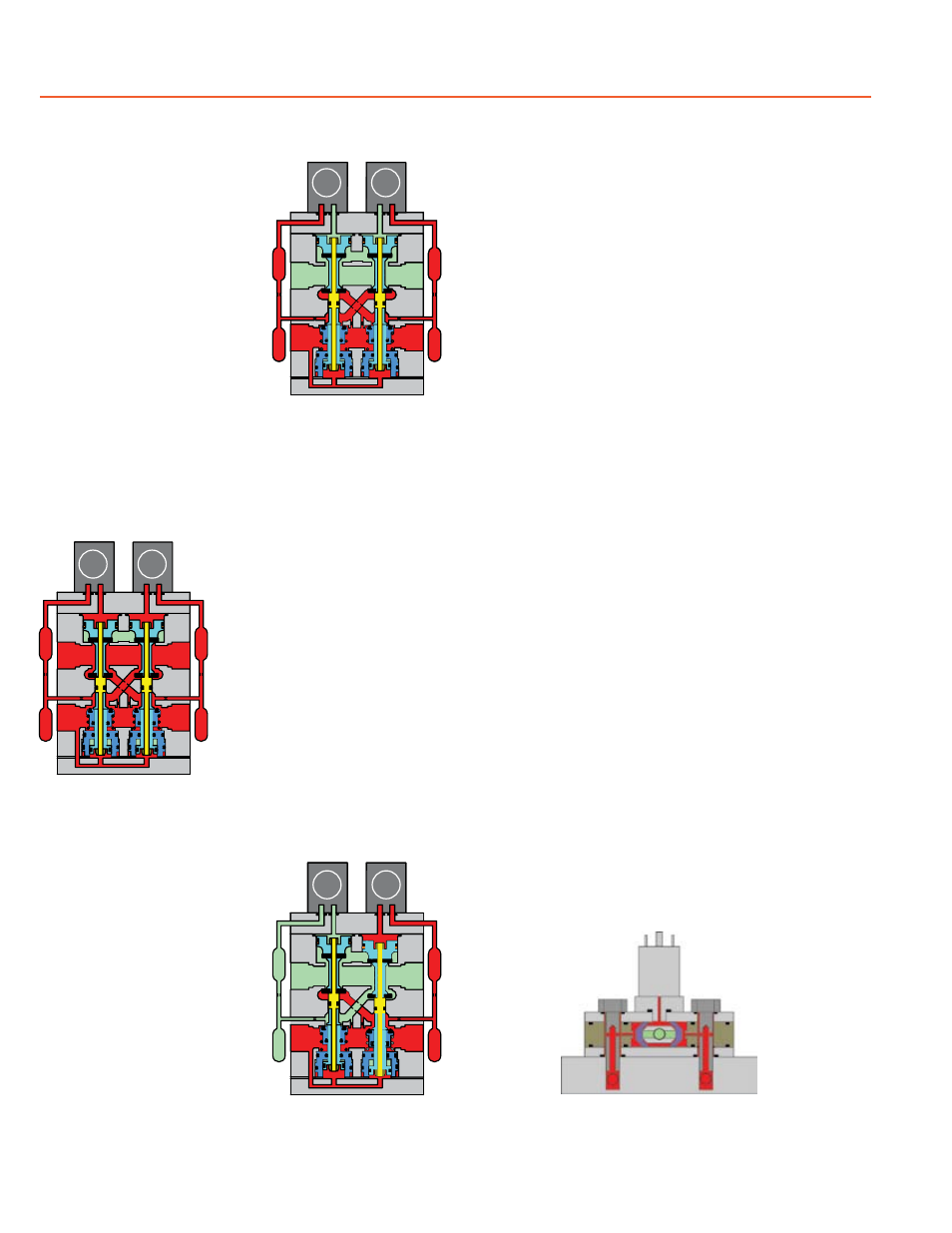
Valve de-actuated
(ready-to-run):
The flow of inlet air pressure
into the crossover passages
from the inlet chamber is
restricted by orifices that allow
air pressure to bypass the lower
inlet poppets. Flow is sufficient
to quickly pressurize the pilot
supply/timing chambers on both
sides A and B. The upper inlet
poppets prevent air flow from
the crossover passages into the
outlet chamber. Air pressure
acting on the inlet poppets and
return pistons securely hold
the valve elements in the de-
actuated position. (Internal air
passages shown out of the valve
body for clarity.)
Valve actuated:
Energizing the pilot solenoids
simultaneously applies pressure
to both pistons, forcing the
internal parts to move to their
actuated position, where inlet
air flow to outlet is open and
both exhaust poppets are
closed. The outlet is then quickly
pressurized, and pressure in
the inlet, crossovers, outlet, and
timing chambers are quickly
equalized. De-energizing the
main solenoids causes the valve
elements to return to the ready-
to-run (de-actuated) position.
Asynchronous operation:
If the valve elements operate
in a sufficiently asynchronous
manner on ACTUATION, the
valve will shift into a position
where one crossover and its
related timing chambers will
be exhausted, and the other
crossover and its related timing
chambers will be pressurized.
In the illustration, side B is in the
de-actuated position, but has
no pilot air available to actuate
with and has full pressure on its
upper and lower inlet poppets and return piston to hold it in
place. Inlet air flow on side B into its crossover is restricted
and flows through the open upper inlet poppet on side A,
through the outlet into the the exhaust port, and from the
exhaust port to atmosphere. Residual pressure in the outlet
is less than 1% of inlet pressure.
Once the main solenoids are de-energized, actuating pressure
is removed from the top of the main pistons and then the
lower inlet poppet return spring along with inlet air pressure
acting on the side A return piston will push side A back into
the de-actuated position. Inlet air pressurizes the crossovers
and volume chambers. Pressure in the crossovers helps
hold the upper inlet poppets on seat. The valve will then be
in the ready-to-run position. On the next attempt to actuate
normally, if side B is still unable to actuate synchronously
with side A, the same sequence of events described above
will occur again.
WARNING:
If asynchronous operation occurs while DE-ACTUATING,
the pilot supply/timing chambers on one side will still be
exhausted as described above. However, this could be a
temporary situation because the cause of the asynchronous
operation may be able to correct itself allowing the stuck or
slow acting side of the valve to eventually move back into
the de-actuated position. Once the slow or stuck side has
de-actuated, the pilot supply/timing chambers that were
exhausted will then repressurize. If an external monitoring
system is only checking the status indicator periodically this
fault signal could be missed. The machine’s safety system
must be designed to ensure that this does not cause a
hazardous situation.
Status indicator:
The status indicator pressure switch will actuate when the
main valve is operating normally, and will de-actuate when
the main valve operation is sufficiently asynchronous or inlet
pressure is removed. This device is not part of the valve
lock-out function, but, rather, only reports the status of the
main valve.
Status indicator in normal
ready-to-run position.
.004.004
.004
B
A
EXHAUST
OUTLET
INLET
Valve actuated.
B
A
EXHAUST
OUTLET
INLET
Valve ready-to-run.
Valve in restricted outlet
to exhaust state.
B
A
EXHAUST
OUTLET
INLET
ROSS CONTROLS
®