10 pin mini cable, Outlet port pressure monitoring wiring kit, J-box wiring – Ross Controls CATEGORY 4 - 3_2 VALVES SERIES DM2 C, E User Manual
Page 16
www.rosscontrols.com
3
10 Pin
Pin #
Port 2
Pin #
Port 3
Pin #
Port 4
Pin #
Port 1
Pin #
1
2
3
4
5
6
7
8
9 10
1
2
3
4
5
6
7
8
9
10
1
1
1
1
3
3
3
3
2
2
2
2
4
4
4
4
1
1
1
1
2
2
2
2
3
3
3
3
5
5
5
5
4
4
4
4
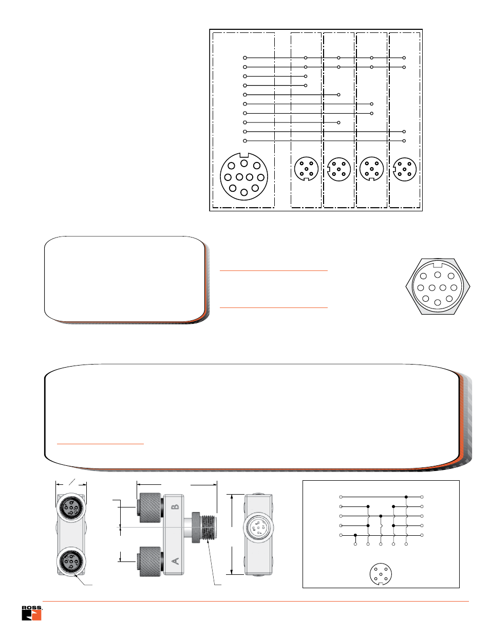
J-Box Wiring
10 PIN MINI Cable
Kit Number
Length (feet)
2253H77
12
2254H77
20
2255H77
30
2256H77
50
These cables have a 10-pin MINI connector
for connecting the J-Box kits above to the
user’s control system. Kits include one
cable with connector and cord grip.
Cable conductors are 18 gage wire.
DESCRIPTION:
1
3
2
4
5
7
6
8
9
10
Wire Colors:
Orange
Blue
White/black
Red/black
Green/black
Orange/black
Red
Green/yellow
Black
White
PIN #
1
2
3
4
5
6
7
8
9
10
(17)
0.7
(10)
0.4
(40) 1.6
(40)
1.6
M12x1 Female
M12x1 Male
O
0.6
Some customers prefer to monitor downstream pressure in addition to using the DM
2®
or DM
1
Series valve. A con-
venient way to do this is to install a pressure switch in the extra outlet port that is provided on the valve. The Outlet
Port Pressure Monitoring wiring kit can be used with one of the J-Box kits above to split one of the M12 ports on the
J-Box so that a pressure switch can be wired in as well. These kits consist of one port splitter (a Tee with three M12
connectors) and one M12-DIN cable (1 meter).
Pressure switch not included. A pressure switch is available separately - order part number 586A86.
Outlet Port Pressure Monitoring Wiring Kit
Kit Number 2251H77
DESCRIPTION:
3
4
5
FEMALE
A
5
1
2
3
4
5
1
2
3
4
1
2
MALE
FEMALE
B
1
3
2
4
5
PORT SPLITTER