Overview of dm, Series c double valve function – Ross Controls CATEGORY 4 - 3_2 VALVES SERIES DM2 C, E User Manual
Page 11
ROSS CONTROLS
®
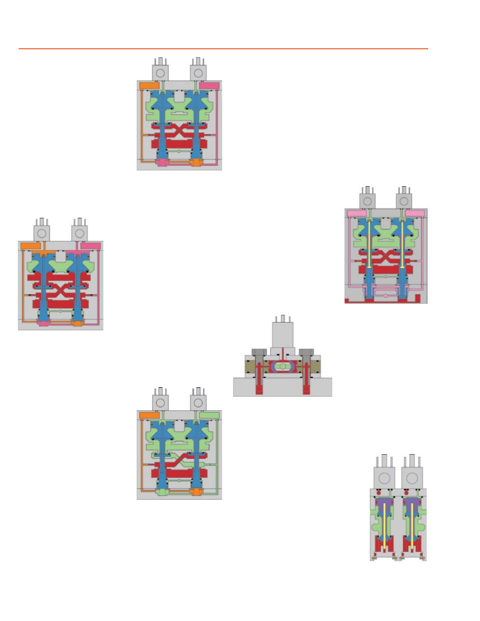
The flow of inlet air pressure
into the crossover passages
is restricted by the size of the
passage between the stem and
the valve body opening. Flow is
sufficient to quickly pressurize
pilot supply/timing chambers A
and B. The inlet poppets prevent
air flow from crossover passa-
ges into the outlet chamber. Air
pressure acting on the inlet pop-
pets and return pistons securely
hold the valve elements in the
closed position.(Air passages
shown out of position and re-
set adapter omitted for clarity.)
Energizing the pilot valves
simultaneously applies pressure
to both pistons, forcing the internal
parts to move to their actuated
(open) position, where inlet air
flow to crossover passages is
fully open, inlet poppets are
fully open and exhaust poppets
are fully closed. The outlet is
then quickly pressurized, and
pressure in the inlet, crossovers,
outlet, and timing chambers are
quickly equalized.
De-energizing the pilots quickly
causes the valve elements
to return to the ready-to-run
position.
Whenever the valve elements
o p e r a t e i n a s u f f i c i e n t l y
asynchronous manner, either
on actuation or de-actuation,
the valve will move to a locked-
out position. In the locked-out
position, one crossover and
its related timing chamber will
be exhausted, and the other
crossover and its related timing
chamber will be fully pressurized.
The valve element (side B) that
is partially actuated has pilot air
available to fully actuate it, but no
air pressure on the return piston to
fully de-actuate the valve element.
Air pressure in the crossover acts
on the differential of side B stem
diameters creating a latching force.
Side A is in a fully closed position, and has no pilot air available
to actuate, but has full pressure on the inlet poppet and return
piston to hold the element in the fully closed position.
Inlet air flow on side A into its crossover is restricted, and
flows through the open inlet poppet on side B, through the
outlet into the the exhaust port, and from the exhaust port to
atmosphere. Residual pressure in the outlet is less than 1% of
inlet pressure.
The return springs are limited in travel, and can only return the
valve elements to the intermediate (locked-out) position. Sufficient
air pressure acting on the return pistons is needed to return the
valve elements to a fully closed position.
The valve will remain in the locked-out position, even if the inlet
air supply is removed and re-applied. A remote reset signal must
be applied to reset the valve.
Reset is accomplished by
momentarily pressurizing the
reset port. Actuation of the reset
piston physically pushes the main
valve elements to their closed
position. Inlet air fully pressurizes
the crossovers and holds the inlet
poppets on seat. Actuation of
the reset piston opens the reset
poppet, thereby, immediately
exhausting pilot supply air, thus,
preventing valve operation during
reset. (Reset adapter added to
illustration.)
De-actuation of reset pistons
causes the reset poppets to
close and pilot supply to fully
pressurize.
Reset pressure can be applied
by a remote 3/2 normally
closed valve, or from an
optional 3/2 normally closed
solenoid mounted on the reset
adapter.
The optional status indicator pressure switch will actuate when
the main valve is operating normally, and will de-actuate when
the main valve is in the locked-out position or inlet pressure
is removed. This device is not part
of the valve lockout function, but,
rather, only reports the status of the
main valve.
Size 12 and 30 valves require
relatively large pilots to actuate and
de-actuate the main valve elements.
In order to achieve extremely quick
valve response for such large pilots,
a 2-stage solenoid pilot system is
incorporated into the design. This
keeps the required electrical current
to operate the pilots to a minimum.
Overview of DM
2®
Series C Double Valve Function
Status indicator (optional) in
normal ready to run position.
Size 12 & 30 pilots.
Valve ready to run.
EXHAUST
OUTLET
INLET
A
B
Valve actuated.
EXHAUST
OUTLET
INLET
A
B
Valve locked-out.
EXHAUST
OUTLET
INLET
A
B
Valve being reset.
EXHAUST
OUTLET
INLET
A
B