SaltDogg LS10 Liquid Spay System User Manual
Page 6
6
9049 Tyler Blvd. • Mentor, Ohio 44060
Phone (440) 974-8888 • Fax (800) 841-8003
www.saltdogg.com
10. Assembly enclosure assembly LS102 to bracket, making sure that enough space left to open
enclosure door.
11. Plumb: Reservoir, ball valve, filter, pump enclosure, and spray nozzles according to plumbing
schematic using supplied fittings, hose, and hose clamps. Do not use Teflon tape on threads. Use
liquid thread sealant.
12. In order to install liquid spray nozzles, 2 holes 11/16" diameter must be drilled in chute. Or
nozzles can be installed above spreader conveyor chain ( some custom bracket fabrication is
required).
Cab Controller Installation Instructions FIGs 10-12
1. Install cab controller (#WSE1) in cab for convenient driver operation. Mounting bracket and fasten-
ers included.
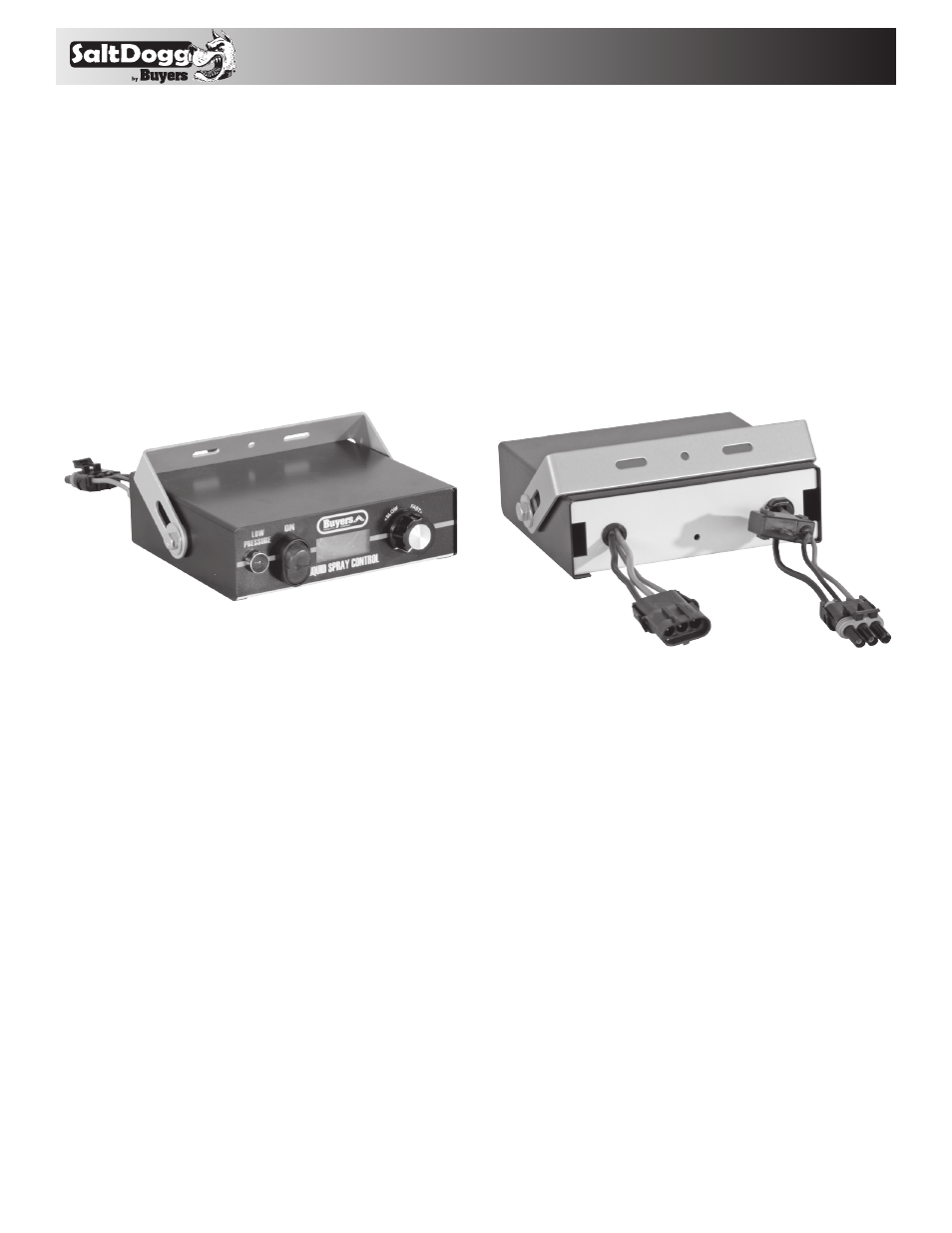
Fig. 10 WSE1 Cab Controller, front view
Fig. 10 WSE1 Cab Controller, rear view
WSE25
25' Cable Connector
WSE24
8' Cable Connector
2. Route 8' wire harness (#WSE24) under dash from controller (#WSE1) to truck’s fuse panel.
3. Ground “black” wire from controller to truck frame or truck’s battery (not dash).
4. Attach “green” wire in 8' wire harness (#WSE24) to a fused and keyed 15 Amp hot wire circuit.
5. Connect main power “white” wire in 8' wire harness (#WSE24) to fuse box that is “hot” full time or
to battery “positive”.
6. Route the 25' wire harness (#WSE25) from the rear of the spreader to the cab. Plug connector on
controller (#WSE1) to the connector on pump harness (#WSE25).
Fig. 7