Caution – American Dynamics Tyco 8 User Manual
Page 22
Installing IP SpeedDome Ultra 8 with a RHOPN Pendant Mounting
4-4
Installation Guide
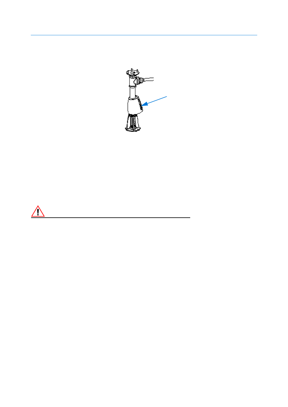
It is suggested you position the cover (A) as shown in Figure 4-5 to aid in the connection of the
prepared pendant housing as described in Procedure 4-2.
Figure 4-5 Recommended cover position during pendant connection
If a junction box or patch panel is being used:
19 Prepare cabling of sufficient length to ensure connection of the IP SpeedDome to the junction
box/patch panel and to enable easy servicing and then route cable (H) through the pipe tee (G)
and the pipe (F) as shown in Figure 4-3.
If a junction box or patch panel is not being used:
20 Ensure that the appropriate cables are in place for the installation and then route cable (H)
through the pipe tee (G) and the pipe (F) as shown in Figure 4-3.
Caution
To reduce the risk of cable damage caused by excessive ‘pull back’ it is recommended that you only pass
enough cable through the support to facilitate connection.
21 Pass the cable through the top of the support and fold the incoming cables back on
themselves.
22 Remove 2.5-3.8cm (1-1.5in) of jacket from the cable end(s) and install power and data
connectors supplied. See Pin Outs for the IP SpeedDome Ultra 8 on page 7-2 for more details.
A