American Dynamics Tyco 8 User Manual
Page 12
3-2
Procedure 3-1 describes how to prepare the hardmount housing before attaching the SDU8.
Procedure 3-1 Preparing and installing the Indoor Hardmount Housing
1 Using template supplied, cut a hole in the ceiling.
Figure 3-1 Cutting hole using template
If a junction box or patch panel is being used then:
2 Prepare cabling of sufficient length to ensure connection of the IP SpeedDome® to the junction
box/patch panel and to enable easy servicing.
If a junction box or patch panel is not being used then, ensure that the appropriate cables are in
place for the installation.
3 Remove the hardmount housing from packaging.
4 Remove the two lock screws and remove the hardmount cover to expose the connectors and
settings at the top of the Hardmount.
5 Remove 2.5-3.8cm (1-1.5in) of jacket from the cable end(s) and install power and data
connectors supplied. See Pin Outs for the IP SpeedDome Ultra 8 on page 7-2 for more details.
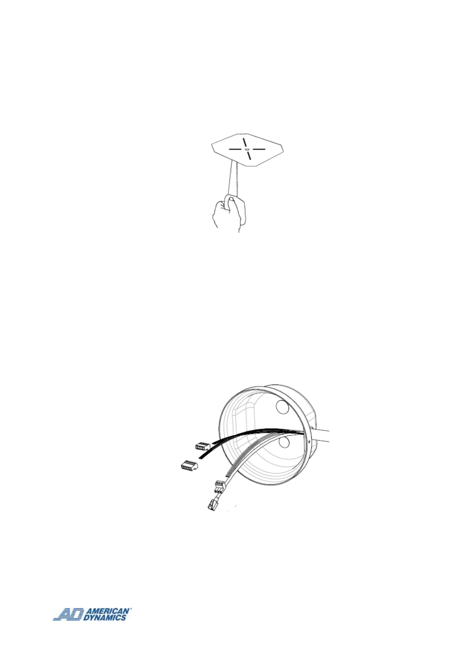
Figure 3-2 Cabling the Hardmount cover
6 Pass the cable through the knockout hole in the hardmount cover as shown in Figure 3-2.
7 Plug the power and data connectors from the incoming cable to the corresponding to
connectors on the pigtail leads on the board.
8 Reattach the cover plate.