Typical layout, Hydraulic systems – Ramsey Winch H930 Dow-Lok W/Counterbalance Valve, Less Brake User Manual
Page 6
4
HYDRAULIC SYSTEMS
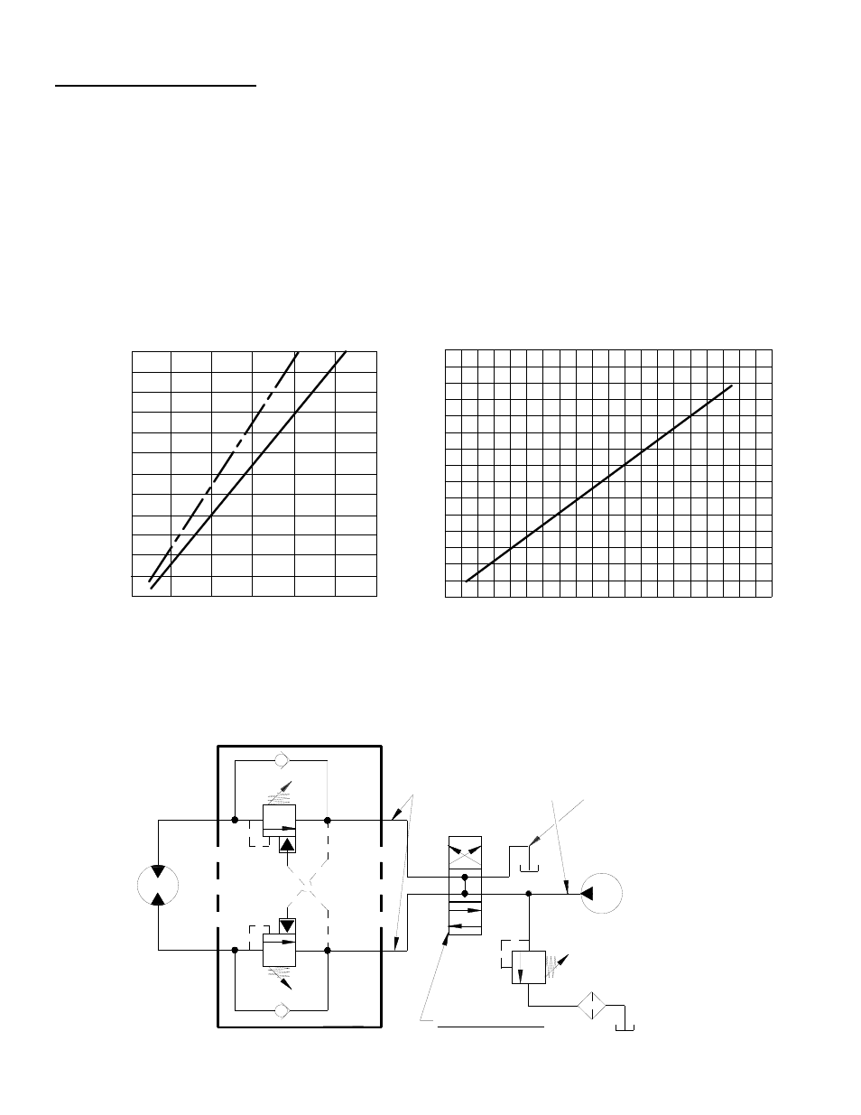
Refer to the performance charts, below, to properly match your hydraulic system to the H930 Series Winch perform-
ance. The charts consist of: (1) Line speed, first layer (F.P.M.) vs. gallons per minute (G.P.M.) and (2) Line pull
(lbs.) first layer vs. working pressure (P.S.I). STATIC (solid line) refers to hoisting a suspended load from rest; DY-
NAMIC (dotted line) refers to maintaining the motion of a moving load.
Performance based on a motor displacement of 24 cubic inches with 35 GPM maximum flow rate. See page 14 for
motor port size.
H930 Performance
30,000 Lb. Duty Rating
41:1 Gear Ratio
CONTROL VALVE
3 POSITION, 4 WAY VALVE
(MOTOR OR CYLINDER SPOOL)
HIGH PRESSURE LINE
DUAL-A & B PORT CONTROL
B
MOTOR A
TYPICAL LAYOUT
LOW PRESSURE LINE
PUMP
GALLONS PER MINUTE
20
LINE
PULL, LBS., FIRST
LAYER
5,000
0
0
20,000
15,000
10,000
30,000
25,000
LINE SPEE
D, FPM, FIRST LAYER
3,000
WORKING PRESSURE, P.S.I.
2,000
1,000
0
0
10
D
YN
AM
IC
ST
AT
IC
5
10
15
30
35
- ATV 2500 ROCKER SWITCH 256117 (4 pages)
- ATV 2500 ROCKER SWITCH FOR WIRELESS REMOTE 256118 (4 pages)
- ATV REPLACEMENT MINI ROCKER SWITCH 256128 (8 pages)
- ATV REPLACEMENT MINI ROCKER SWITCH FOR WIRELESS 256129 (4 pages)
- ATV SYNTHETIC ROPE KIT 251268 (4 pages)
- ATV SYNTHETIC ROPE KIT, LESS HOOK TAMARACK 251294 (4 pages)
- ATV SYNTHETIC ROPE KIT, TAMARACK 251297 (4 pages)
- ATV WINCH QUICK MOUNT KIT 251076 (4 pages)
- ATV_BADGER 2500 BRAKE 256116 (4 pages)
- ATV UNIVERSAL WIRELESS REMOTE FOR ATV WINCHES (24 pages)
- ATV WIRELESS REMOTE FOR ATV (12 pages)
- ATV WIRELESS REMOTE FOR ATV TAMARACK (12 pages)
- ATV WIRELESS REMOTE FOR BADGER 2500 (6 pages)
- ATV 8 WITH REMOTE (36 pages)
- ATV-2500 (24 pages)
- ATV-2500 (W_Brake) (16 pages)
- ATV-2500 TAMARACK W_MINI ROCKER SWITCH (16 pages)
- ATV-2500 W_MINI ROCKER SWITCH (16 pages)
- ATV-3000 (16 pages)
- ATV-3000 TAMARACK W_SYNTHETIC ROPE (12 pages)
- ATV-3000 W_MINI ROCKER SWITCH (16 pages)
- ATV-3000 W_SYNTHETIC ROPE (12 pages)
- UTV Honcho 5000 (12 pages)
- PATRIOT 12000_15000 SUN GEAR REPLACEMENT KIT 251275 (3 pages)
- PATRIOT 15000 BRAKE REPLACEMENT KIT 251252 (5 pages)
- REP-8000 24V MOTOR REPLACEMENT 251277 (4 pages)
- SAFETY ON_OFF SWITCH KIT 282062, 282063 (20 pages)
- SYNTHETIC ROPE KIT 251262 (8 pages)
- UNIV. WIRELESS REMOTE FOR FR. MOUNT WINCHES 251200-251202 (8 pages)
- BADGER 2500 (8 pages)
- BADGER 2500 W_PENDANT REMOTE (12 pages)
- BADGER 2500 W_WIRELESS REMOTE (10 pages)
- PATRIOT 12000 (12 pages)
- PATRIOT 15000 (12 pages)
- PATRIOT 15000 (42 pages)
- PATRIOT 15000 W_LOWERED SOLENOID (12 pages)
- PATRIOT 6000, 8000 & 9500 (12 pages)
- PATRIOT 6000, 8000 & 9500 (46 pages)
- PATRIOT 9500 UT (12 pages)
- PATRIOT 9500 W_SYNTHETIC ROPE (12 pages)
- PATRIOT PROFILE 12000 (11 pages)
- PATRIOT PROFILE 12000 (50 pages)
- PATRIOT PROFILE 6000, 8000, & 9500 (66 pages)
- PATRIOT PROFILE 9500 UT (12 pages)
- PATRIOT PROFILE-6000_8000_9000_9500 (16 pages)