Ramsey Winch H930 Dow-Lok W/Counterbalance Valve, Less Brake User Manual
Page 13
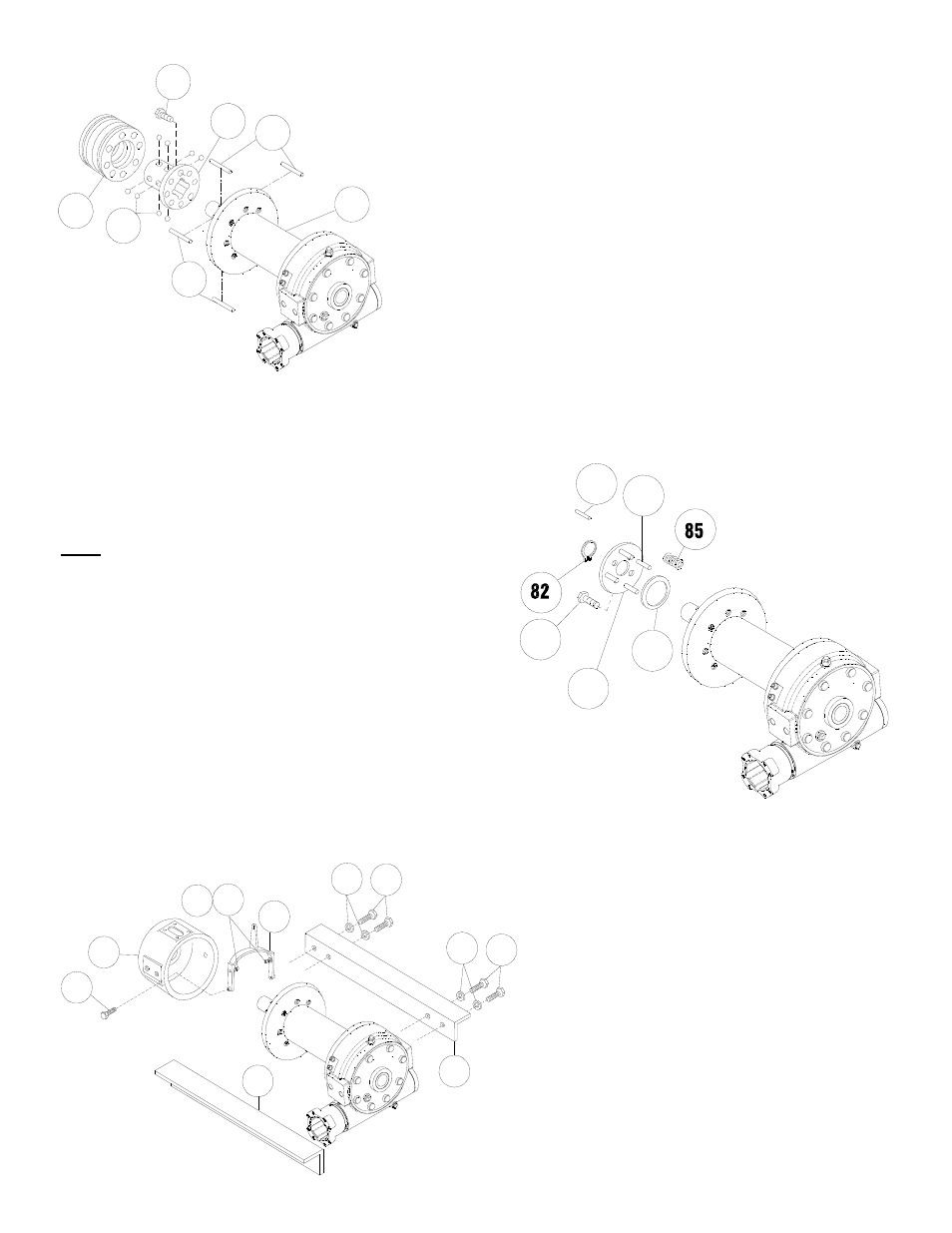
11
(17 )
Place clutch (item #9) over end of drum shaft. Align the clutch over
the pilot bushing in drum. Install the eight capscrews (item #44)
and torque the capscrews to 103 ft. lbs. (139 Nm.) to securely seat
the clutch to the drum.
Rotate the drum to align the clutch slots with the shaft keyways.
Lightly grease four dowel pins, (item #77) and eight balls (item #32)
with molybdenum disulfide or graphite bearing grease. Insert the four
dowel pins and eight balls. In the engaged position the balls are nearly
flush with the clutch.
Lightly grease the internal and external groove and bore in locking ring
(item #10) and clutch (item #9).
Slide locking ring onto the clutch. When fully engaged, the locking
ring touches the clutch flange and there is .71 to .73 inches between
the end of the locking ring and the end of the clutch.
(18)
Lightly grease the four springs (item #85) and place over four
roll pins on retainer plate (item #76).
NOTE: If roll pins (items #76 N) are damaged, remove
pins from plate and install new pins as follows:
Insert four roll pins (item #76) into same retainer plate holes.
Drive pins into plate until pins extend 5/16" thru, the clutch
housing side, of retainer plate. Drive roll pins (item #78) into
ends of (item #76) pins, extending 5/16" beyond retainer plate,
until ends of roll pins are flush. Check to make sure that roll
pins still extend 5/16" through retainer plate.
Install spacer (item #28), retainer plate, with springs, and se-
cure to clutch using four capscrews (item #38). Torque cap-
screws to 9.7 ft./lbs. (13 Nm.) each. Firmly seat the retainer
ring (item #82) into drum shaft groove.
(19)
Set the yoke (item #30) so that the screw heads
(item #52) engage the external groove in the
locking ring. Push the clutch housing (item #19)
onto the drum shaft and latch the shifter assem-
bly in the engaged "IN" position. Insert the two
capscrews (item #47) and securely tighten.
Attach mounting angles (item #4) to winch as-
sembly using four capscrews (item #48), at
clutch housing, and four capscrews (item #49),
at gear housing, with lockwasher (item #64).
Torque capscrews to 500 ft. lbs. (678 Nm.) each.
77
77
15
9
32
10
44
76
78
38
28
79
52 57
47
19
30
4
48
64
64
4
49