Operation, Case front controls – Lincoln Electric IM10144 POWER WAVE S700 User Manual
Page 32
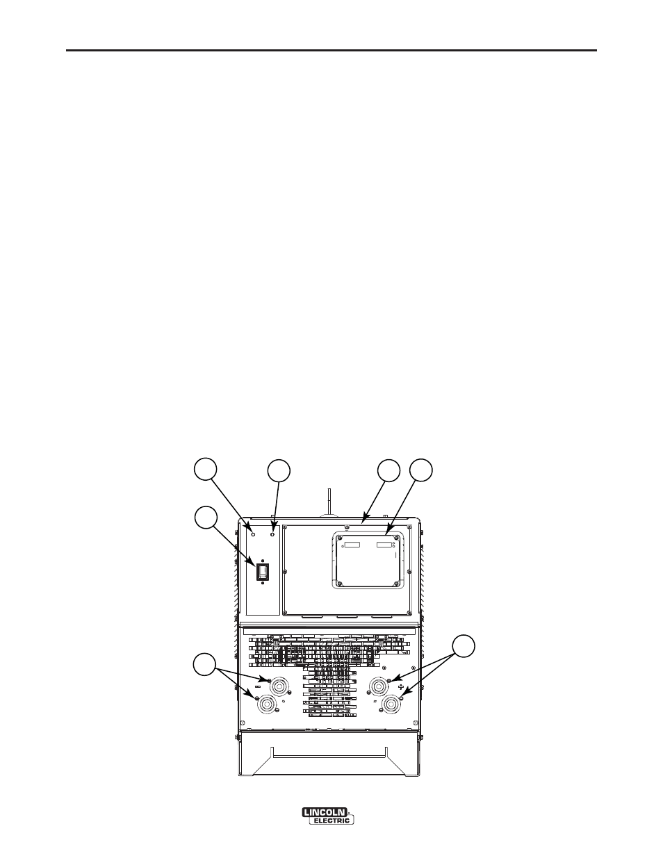
CASE FRONT CONTROLS
(See Figure B.1)
1. POWER SWITCH: Controls input power to the Power Wave
®
S700.
2. STATUS LED - A two color light that indicates the condition of the system. Normal
operation is a steady green light. Error conditions are detailed in
the Trouble Shooting Section of this manual. A red light indicates
an error.
NOTE: The Power Wave® S700ʼs status light will flash green for up to 60 sec-
onds when the machine is first turned on. This is a normal situation as the
machine goes through a self test at power up.
3. THERMAL LED - A yellow light that comes on when an over-temperature condition
occurs. Output is disabled until the machine cools down. When
cool, the light goes out and output is re-enabled.
4. ACCESS PANEL - This panel provides access to the control board compartment.
5. POSITIVE OUTPUT STUDS
6. NEGATIVE OUTPUT STUDS
7. METER - Optional kit used to display arc current and voltage while welding in any
mode.
B-6
OPERATION
B-6
POWER WAVE
®
S700
1
3
4
5
6
2
7
(Optional)
FIGURE B.1
- Invertec V310-T DC (2 pages)
- VANTAGE 500 (CE) 11575 (50 pages)
- INVERTEC V350-PRO SVM152-A (155 pages)
- IMVERTEC V160-T (36 pages)
- IDEALARC CV-300 (112 pages)
- INVERTEC POWER WAVE 450 SVM112-B (293 pages)
- AUTO-DARKENING HELMET IM10001 (12 pages)
- IM10111 IDEALARC R3R-500-I (28 pages)
- IM10110 IDEALARC R3R-400 (25 pages)
- IM10051 INVERTEC V311-T AC_DC (38 pages)
- IM10059 SQUARE WAVE TIG 175 (30 pages)
- IM10096 POWER MIG 256 (38 pages)
- IM10096 POWER MIG 256 (37 pages)
- IM10105 POWER MIG 350MP (47 pages)
- IM10115 FLEXTEC 650 (42 pages)
- IM10132 FLEXTEC 650 (56 pages)
- IM10132 FLEXTEC 650 (36 pages)
- IM10018 IDEALARC DC-600 VRD (55 pages)
- IM10107 IDEALARC DC-400 (40 pages)
- IM10062 FLEXTEC 450 (72 pages)
- IM10091 FLEXTEC 450 CE (40 pages)
- IM10094 RED-D-ARC FX450 (31 pages)
- IM10157 12_24V 10A Auto HF Household Charger (16 pages)
- IM10139 JUMP STARTER (12 pages)
- IM10149 POWER WAVE ADVANCED MODULE (46 pages)
- IM10102 AIR VANTAGE 650 (60 pages)
- IM10103 AIR VANTAGE 700 (AU) (57 pages)
- IM10065 AIR VANTAGE 500 CUMMINS (54 pages)
- IM10066 AIR VANTAGE 500 (AU) (56 pages)
- IM10041 VANTAGE 500 CUMMINS (56 pages)
- IM10128 AIR VANTAGE 500 KUBOTA (AU) (56 pages)
- IM10090 ARC TRACKER (48 pages)
- IM10147 AUTO-DARKENING HELMET (12 pages)
- IM10087 AutoDrive 19 CONTROLLER (28 pages)
- IM10125 AutoDrive 19 TANDEM (34 pages)
- IM10069 AutoDrive 4R100 (32 pages)
- IM10145 AUTOPRO 20 (24 pages)
- IM10025 BIG RED 500 (40 pages)
- IM10019 BIG RED 600 (41 pages)
- IM10005 BULLDOG 140 (46 pages)
- IM10074 BULLDOG 5500 (56 pages)
- IM10067 CENTURY AC120 (20 pages)
- IM10109 CIRCULATOR (33 pages)
- IM10109 CIRCULATOR (36 pages)
- IM10153 CLASSIC 300 HE (60 pages)