Installation, A-17 – Lincoln Electric IM10144 POWER WAVE S700 User Manual
Page 24
If Sense Leads ARE NOT Used:
• Avoid common current paths. Current from adja-
cent arcs can induce voltage into each others cur-
rent paths that can be misinterpreted by the power
sources and result in arc interference.
If Sense Leads ARE Used:
• Position the sense leads out of the path of the weld
current. Especially any current paths common to
adjacent arcs. Current from adjacent arcs can
induce voltage into each others current paths that
can be misinterpreted by the power sources, and
result in arc interference.
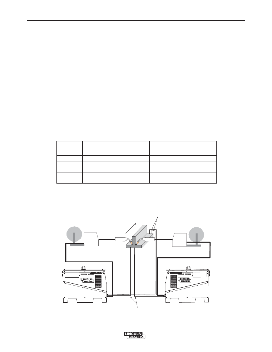
• For longitudinal applications, connect all work leads
at one end of the weldment, and all of the work volt-
age sense leads at the opposite end of the weld-
ment. Perform welding in the direction away from
the work leads and toward the sense leads.
(See Figure A.11)
DIRECTION
OF TRAVEL
CONNECT ALL
WORK LEADS AT
THE BEGINNING
OF THE WELD.
CONNECT ALL SENSE
LEADS AT THE END
OF THE WELD.
FIGURE A.11
A-17
INSTALLATION
POWER WAVE
®
S700
A-17
General Guidelines for Voltage Sense Leads
Sense leads should be attached as close to the weld
as practical, and out of the weld current path when
possible. In extremely sensitive applications it may be
necessary to route cables that contain the sense
leads away from the electrode and work welding
cables.
Voltage sense leads requirements are based on the
weld process (See Table A.2)
VOLTAGE SENSING CONSIDERATIONS
FOR MULTIPLE ARC SYSTEMS
Special care must be taken when more than one arc
is welding simultaneously on a single part. Multiple arc
applications do not necessarily dictate the use of
remote work voltage sense leads, but they are strong-
ly recommended.
Process
GMAW
GMAW-P
FCAW
GTAW
SMAW
Electrode Voltage Sensing
(1)
67 lead
67 lead required
67 lead required
67 lead required
Voltage sense at studs
Voltage sense at studs
Work Voltage Sensing
(2)
21 lead
21 lead optional
(3)
21 lead optional
(3)
21 lead optional
(3)
Voltage sense at studs
Voltage sense at studs
TABLE A.2
(1)
The electrode voltage sense lead (67) is automatically enabled by the weld process, and integral to the 5 pin arclink control cable (K1543-
xx).
(2)
When a work voltage sense lead (21) is connected the power source will automatically switch over to using this feedback (if the auto
sense feature is enabled).
(3)
Negative polarity semi-automatic process operation WITHOUT use of a remote work sense lead (21) requires the Negative Electrode
Polarity attribute to be set.