Installation, Input connection, Input fuse and supply wire considerations – Lincoln Electric IM10144 POWER WAVE S700 User Manual
Page 11: Input voltage selection, Warning
A-4
INSTALLATION
POWER WAVE
®
S700
A-4
INPUT CONNECTION
ELECTRIC SHOCK can kill.
Only a qualified electrician should
connect the input leads to the
Power Wave
®
S700. Connections
should be made in accordance with all local and
national electrical codes and the connection dia-
grams located on the inside of the
reconnect/input access door of the machine.
Failure to do so may result in bodily injury or
death.
------------------------------------------------------------------------
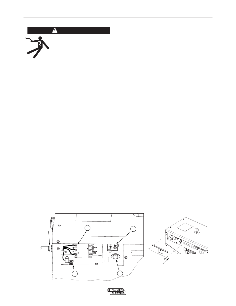
(See Figure A.1)
Use a three-phrase supply line. A 1.75 inch diameter
access hole with strain relief is located on the case
back. Route input power cable through this hole and
connect L1, L2, L3 and ground per connection dia-
grams and National Electric Code. To access the
input power connection block, remove two screws
holding the access door to the side of the machine.
ALWAYS CONNECT THE POWER WAVE GROUND-
ING LUG (LOCATED AS SHOWN IN FIGURE A.1)
TO A PROPER SAFETY (EARTH) GROUND.
Input Power Compartment Controls Description:
1. Input Contactor: Connects 3-phase power to the
welder.
2. Ground Lug: Provides an “Earth Ground” connec-
tion to the welder frame.
3. Auxiliary Reconnect: Allows for easy tap selection
on the auxiliary transformers over the range of input
voltages.
4. Fuse: Protects the auxiliary transformers.
INPUT FUSE AND SUPPLY WIRE
CONSIDERATIONS
Refer to Specification Section for recommended fuse,
wire sizes and type of the copper wires. Fuse the
input circuit with the recommended super lag fuse or
delay type breakers (also called "inverse time" or
"thermal/magnetic" circuit breakers). Choose input
and grounding wire size according to local or national
electrical codes. Using input wire sizes, fuses or cir-
cuit breakers smaller than recommended may result in
"nuisance" shut-offs from welder inrush currents, even
if the machine is not being used at high currents.
INPUT VOLTAGE SELECTION
Welders are shipped connected for the highest input
voltage listed on the rating plate. To move this con-
nection to a different input voltage, see the diagram
located on the inside of the input access door, also
illustrated below. If the Auxiliary lead (indicated as ʻAʼ)
is placed in the wrong position, there are two possible
results. If the lead is placed in a position higher than
the applied line voltage, the welder may not come on
at all. If the Auxiliary lead is placed in a position lower
than the applied line voltage, the welder will not come
on, and the two circuit breakers in the reconnect area
will open. If this occurs, turn off the input voltage,
properly connect the auxiliary lead, reset the breakers,
and try again
WARNING
POWER CONNECTION BLOCK
INPUT CORD STRAIN RELIEF
CONNECT EACH PHASE OF A THREE-PHASE
CONDUCTOR HERE
GROUND CONNECTION
CONNECT GROUND LEAD PER LOCAL
AND NATIONAL ELECTRIC CODE
ROUTE INPUT CORD
THROUGH RELIEF AND
TWIST NUT TO TIGHTEN
INPUT POWER
ACCESS DOOR
1
3
4
2
FIGURE A.1