Lincoln Electric IM10163 FLEX FEED 74 HT User Manual
Page 20
A-13
INSTALLATION
FLEX FEED™ 74 HT
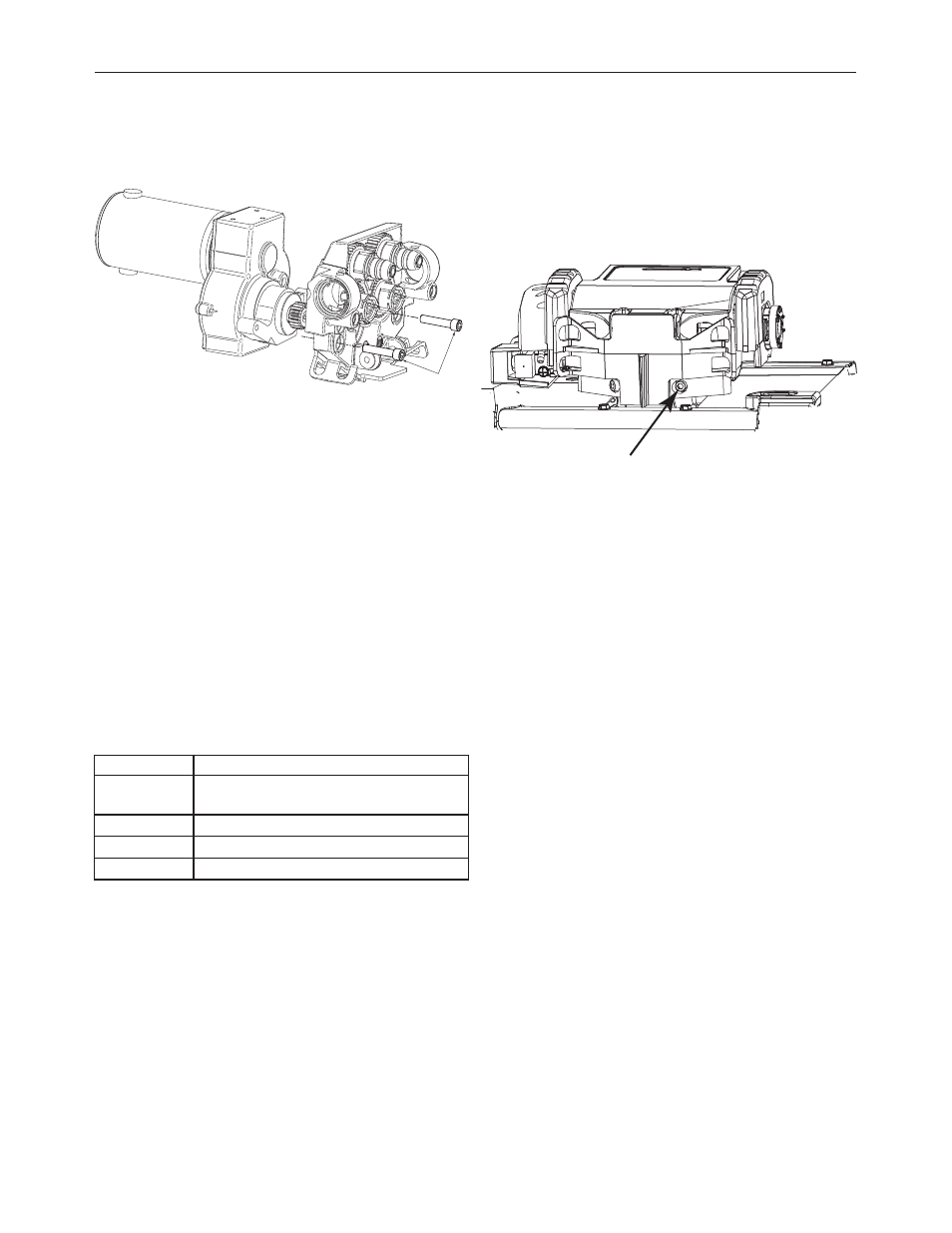
3. Remove the two socket head cap screws securing the
feed plate and remove the feed plate from clamp using
a 1/4” hex key.
FIGURE A.17
4. Remove the screw holding the pinion gear using a
Phillips screw driver. Remove the pinion gear.
5. Install the new pinion gear.
6. Position the feed plate and tighten the socket head cap
screws.
7. Re-assemble the hinge pin and door. Secure the hinge
pin with the set screw.
8. Remove the (4) screws securing the roof with a 5/16”
nut driver.
9. Locate the leads 586 and 515E. The ends of the leads
have pink terminals cable tied into a bundle close to
the pc board.
• 20 tooth pinion gear: connect 586 to 515E
• 30 tooth pinion gear: disconnect 586 to 515E
10. Apply/remove the wire feed speed decal from the
name plate as follows:
Speed Range
Decal
50 – 500 in/min
Default value. Remove any decals applied to the
nameplate.
50 – 700 in/min
M24808-1
1.5 – 12.5 m/min
M24808-2
1.5 – 18 m/min
M24808-3
Decals are located in the literature of the feeder.
ROTATING THE FEED PLATE
1. Turn power OFF at the welding power source.
2. Locate the socket head cap screw at the bottom of the
wire drive. Loosen, but do not remove the screw using
a 1/4” hex key.
FIGURE A.18
3. Rotate the wire drive to the desired position and tighten
the screw.
(2) SOCKET HEAD
CAP SCREWS
SOCKET HEAD CAP SCREW