22 usb connector (usb4), 3 external interface panel connectors, 1 ethernet connector (lan1, lan2) – IEI Integration AFL-08B-N270 v2.30 User Manual
Page 104
AFL-08B-N270 User Manual
Page 104
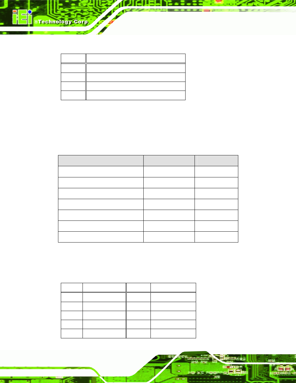
5.2.22 USB Connector (USB4)
5.3 External Interface Panel Connectors
The table below lists the rear panel connectors on the AFL-08B-N270 motherboard.
Pinouts of these connectors can be found in the following sections.
Connector
Type
Label
Ethernet connector
RJ-45
LAN1, LAN2
Power connector
DIN
CN5
Reset button
Push button
CN6
RS-232 serial ports
DB-9
COM1
RS-232/422/485 serial port
DB-9
COM3
SATA connector
SATA connector
SATA2
USB 2.0 connectors
USB 2.0 port
USB3
Table 5-24: Rear Panel Connectors
5.3.1 Ethernet Connector (LAN1, LAN2)
PIN NO.
DESCRIPTION
PIN NO.
DESCRIPTION
1 LAN1_MDI0+ 2 LAN1_MDI0-
3 LAN1_MDI1+ 4 LAN1_MDI1-
5 N/A
6 N/A
7 LAN1_MDI2+ 8 LAN1_MDI2-
9 LAN1_MDI3+ 10 LAN1_MDI3-
PIN NO.
DESCRIPTION
1
USB Power (selected by JP15)
2 D3F-
3 D3F+
4 GND
Table 5-23: USB Connector (USB4) Pinouts
- UPC-V312-D525 v1.02 (176 pages)
- UPC-V312-D525 v1.10 (175 pages)
- UPC-12A_GM45 v1.00 (147 pages)
- UPC-12A_GM45 v2.00 (144 pages)
- UPC-12A_GM45 v2.10 (145 pages)
- UPC-V315-NM70 (148 pages)
- UPC-V315-Screw Driver (1 page)
- UPC-V315-QM77 (148 pages)
- S12ASR v1.12 (110 pages)
- S12ASR v3.00 (118 pages)
- PPC-5xxx-9455 v1.00 (198 pages)
- PPC-5xxx-9455 v1.10 (198 pages)
- PPC-WIDS-51xxA-G41 (152 pages)
- PPC-51xxA-H61 (193 pages)
- PPC-5152-D525 v1.02 (183 pages)
- PPC-5152-D525 v2.10 (185 pages)
- PPC-37xxA-N26 v1.00 (203 pages)
- PPC-37xxA-N26 v1.10 (200 pages)
- PPC-37xx-N270 v1.01 (165 pages)
- PPC-37xx-N270 v2.00 (155 pages)
- PPC-37xx-N270 v2.11 (155 pages)
- PPC-37xx-N270 v2.20 (162 pages)
- ACT-457A (67 pages)
- AFL-4 series-N270 v1.05 (165 pages)
- AFL-4 series-N270 v2.10 (166 pages)
- AFL-4 series-N270 v2.11 (168 pages)
- AFL-4 series-N270 v2.20 (168 pages)
- AFL-W19A_W19B_17D_W15A-GM45 v2.10 (138 pages)
- AFL-W19A_W19B_17D_W15A-GM45 v1.06 (138 pages)
- AFL-W19A_W19B_17D_W15A-GM45 v2.20 (151 pages)
- AFL-W15A_17D-GM45 v3.00 (148 pages)
- AFL-15i-HM55 v1.01 (139 pages)
- AFL-19i-HM55 v2.00 (140 pages)
- AFL-15i-HM55 v1.20 (143 pages)
- AFL-W19A_W19B_17D_W15A-N270 v1.06 (125 pages)
- AFL-W19A_W19B_17D_W15A-N270 v2.20 (124 pages)
- AFL-W19A_17D_W15A-N270 v3.00 (126 pages)
- AFL-15A_15AE-N270_UMN_v1.01.pdf (158 pages)
- AFL-15A-N270 v1.03 (159 pages)
- AFL-15A-N270 v2.10 (159 pages)
- AFL-15A-N270 v2.20 (158 pages)
- AFL-xxA-N26 (152 pages)
- AFL-xxA-N270-Series v1.03 (171 pages)
- AFL-xxA-N270-Series v2.00 (171 pages)
- AFL-xxA-N270-Series v2.11 (170 pages)