3 usb connection (dual connector), Figure 4-15: serial device connector – IEI Integration WAFER-945GSE2 v2.00 User Manual
Page 73
WAFER-945GSE2 3.5" Motherboard
Page 58
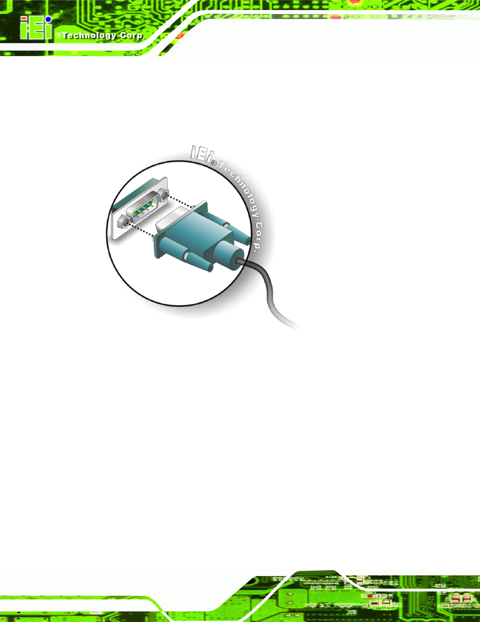
Step 1:
Locate the DB-9 connector. The location of the DB-9 connector is shown in
Chapter 3.
Step 2:
Insert the serial connector.
Insert the DB-9 connector of a serial device into
the DB-9 connector on the external peripheral interface. See Figure 4-15.
Figure 4-15: Serial Device Connector
Step 3:
Secure the connector. Secure the serial device connector to the external
interface by tightening the two retention screws on either side of the connector.
4.7.3 USB Connection (Dual Connector)
The external USB receptacle connectors provide easier and quicker access to external
USB devices. Follow the steps below to connect USB devices to the WAFER-945GSE2.
Step 1:
Locate the USB receptacle connectors. The location of the USB receptacle
connectors are shown in Chapter 3.
Step 2:
Insert a USB plug.
Insert the USB plug of a device into the USB receptacle on
the external peripheral interface. See Figure 4-16.