7 external peripheral interface connection, Xternal, Eripheral – IEI Integration WAFER-945GSE2 v2.00 User Manual
Page 71: Nterface, Onnection, Figure 4-13: dual usb cable connection
WAFER-945GSE2 3.5" Motherboard
Page 56
Step 1:
Locate the connectors. The locations of the USB connectors are shown in
Chapter 3.
WARNING:
If the USB pins are not properly aligned, the USB device can burn out.
Step 2:
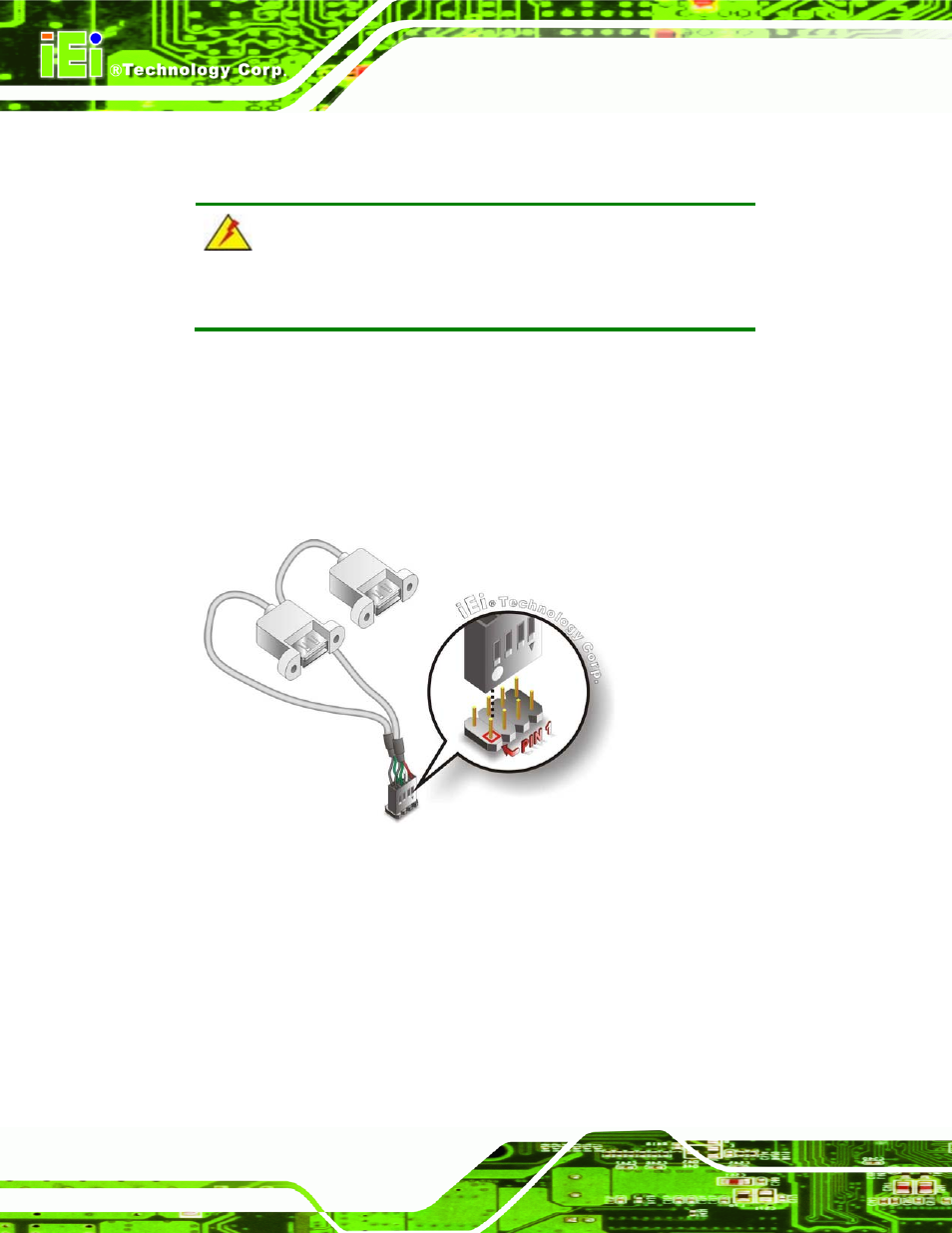
Align the connectors. The cable has two connectors. Correctly align pin 1on
each cable connector with pin 1 on the WAFER-945GSE2 USB connector.
Step 3:
Insert the cable connectors. Once the cable connectors are properly aligned
with the USB connectors on the WAFER-945GSE2, connect the cable
connectors to the on-board connectors. See Figure 4-13.
Figure 4-13: Dual USB Cable Connection
Step 4:
Attach the USB connectors to the chassis. The USB 2.0 connectors each of
two retention screw holes. To secure the connectors to the chassis please refer
to the installation instructions that came with the chassis.
4.7 External Peripheral Interface Connection
This section describes connecting devices to the external connectors on the
WAFER-945GSE2.