6 usb cable (dual port without bracket) (optional) – IEI Integration WAFER-945GSE2 v2.00 User Manual
Page 70
WAFER-945GSE2 3.5" Motherboard
Page 55
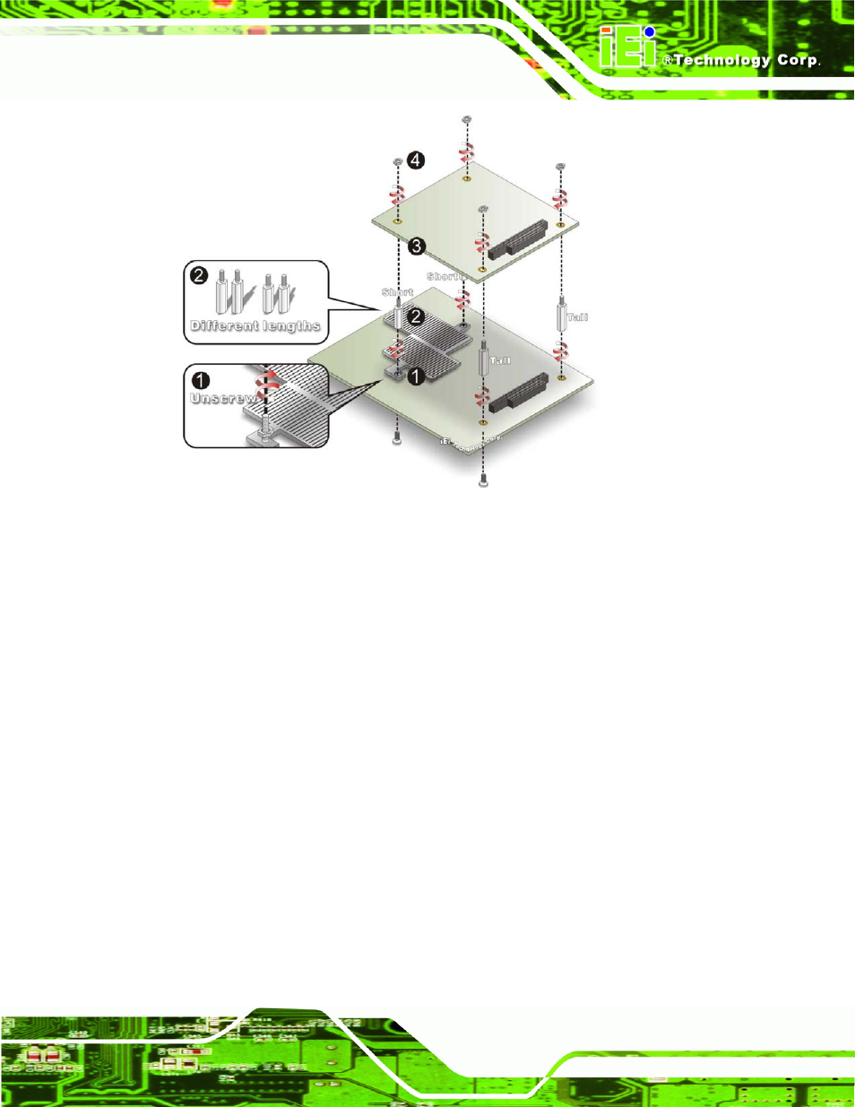
Figure 4-12: WAFER-945GSE2 PC/104 module installation
Step 4:
Remove retention nuts. Remove the two nuts securing the heatsink and two
nuts securing the WAFER-945GSE2 to the chassis.
Step 5:
Attach intermediate poles. Insert the two short plastic intermediate poles into
the bolts securing the heatsink. Insert the two tall plastic intermediate poles.
Step 6:
Align the PC/104 connector. Align the PC/104 module connector with the
corresponding connector on the WAFER-945GSE2 (connector CN2). Gently
push the module down to ensure the connectors are properly connected.
Step 7:
Replace the retention nuts. Screw the four retention nuts onto the
intermediate poles to secure the PC/104 module.
4.6.6 USB Cable (Dual Port without Bracket) (Optional)
The WAFER-945GSE2 is shipped with a dual port USB 2.0 cable. To connect the USB
cable connector, please follow the steps below.
- SPCIE-5100DX (180 pages)
- SPCIE-C2060 v1.01 (200 pages)
- SPCIE-C2060 v2.12 (212 pages)
- SPCIE-C2160 (204 pages)
- SPCIE-C2260-i2 (217 pages)
- ROCKY-3786 v4.0 (175 pages)
- ROCKY-3786 v4.10 (147 pages)
- PCIE-Q350 v1.00 (272 pages)
- PCIE-Q350 v1.12 (250 pages)
- PCIE-Q350 v1.20 (250 pages)
- PCIE-Q350 v1.30 (213 pages)
- PCIE-Q57A (159 pages)
- PCIE-G41A2 (151 pages)
- PCIE-Q670 v1.03 (206 pages)
- PCIE-Q670 v2.00 (205 pages)
- PCIE-H610 (181 pages)
- PCIE-Q870-i2 (217 pages)
- IOWA-LX-600 (159 pages)
- PCISA-945GSE v1.01 (207 pages)
- PCISA-945GSE v1.10 (190 pages)
- PCISA-9652 v1.00 (232 pages)
- PCISA-9652 v1.01 (232 pages)
- PCISA-PV-D4251_N4551_D5251 (145 pages)
- PICOe-945GSE (197 pages)
- PICOe-GM45A (198 pages)
- PICOe-PV-D4251_N4551_D5251 v1.00 (154 pages)
- PICOe-PV-D4251_N4551_D5251 v1.10 (154 pages)
- PICOe-PV-D4251_N4551_D5251 v1.11 (155 pages)
- PICOe-B650 (156 pages)
- PICOe-HM650 (174 pages)
- HYPER-KBN (139 pages)
- SPXE-14S (3 pages)
- SPXE-9S v1.00 (5 pages)
- SPXE-9S v1.1 (6 pages)
- SPE-9S v1.00 (4 pages)
- SPE-9S v1.1 (5 pages)
- SPE-6S (3 pages)
- SPE-4S (4 pages)
- PE-6SD3 (4 pages)
- PE-6SD2 v4.0 (4 pages)
- PE-6SD2 v2.10 (3 pages)
- PE-6SD (3 pages)
- PE-6S3 v1.0 (2 pages)
- PE-6S3 v4.0 (4 pages)
- PE-6S2 (4 pages)