4 audio kit installation, 5 pc/104 module installation, Figure 4-11: audio kit cable connection – IEI Integration WAFER-945GSE2 v2.00 User Manual
Page 69
WAFER-945GSE2 3.5" Motherboard
Page 54
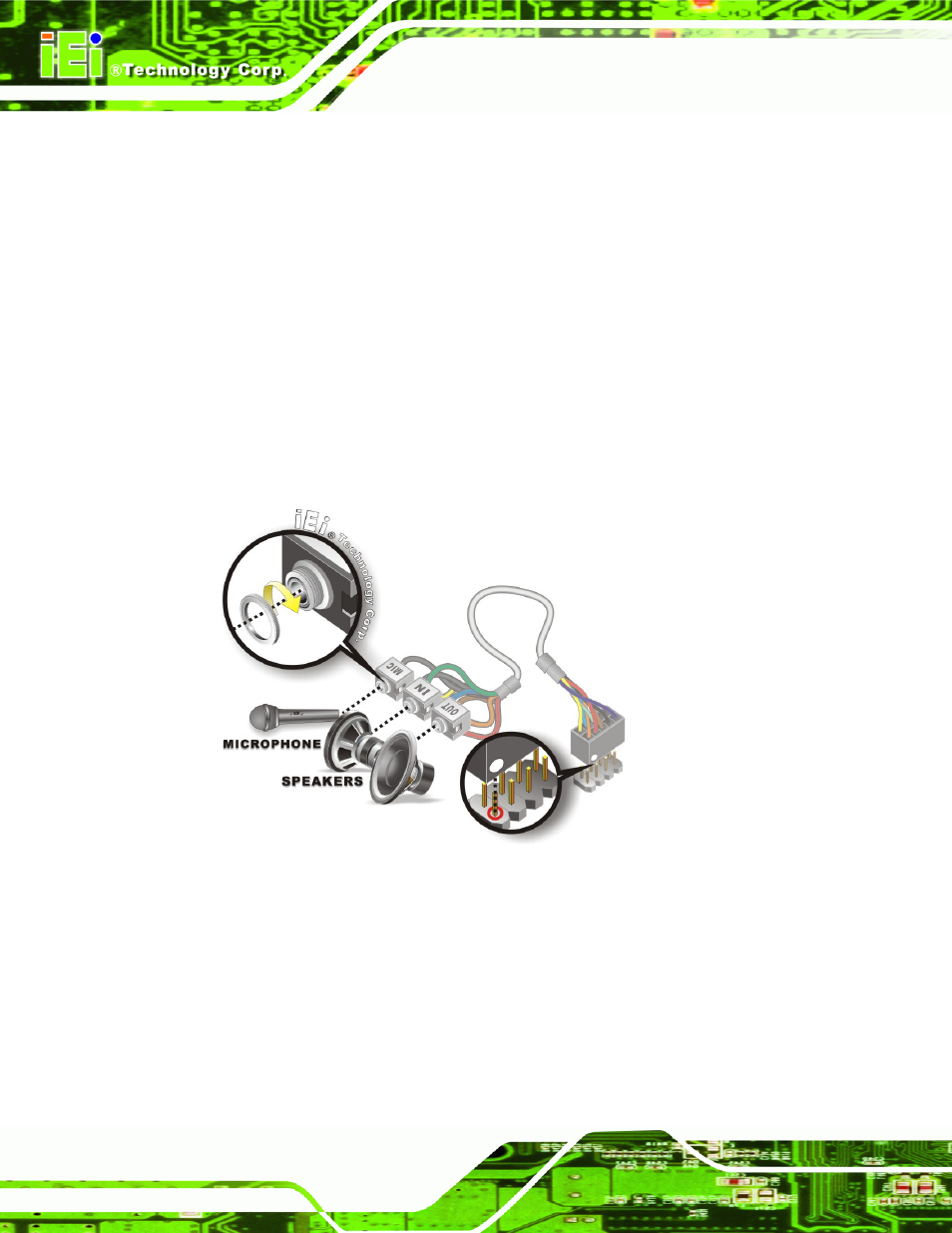
4.6.4 Audio Kit Installation
The Audio Kit that came with the WAFER-945GSE2 connects to the 10-pin audio
connector on the WAFER-945GSE2. The audio kit consists of three audio jacks. One
audio jack, Mic In, connects to a microphone. The remaining two audio jacks, Line-In and
Line-Out, connect to two speakers. To install the audio kit, please refer to the steps below:
Step 1:
Locate the audio connector. The location of the 10-pin audio connector is
shown in Chapter 3.
Step 2:
Align pin 1. Align pin 1 on the on-board connector with pin 1 on the audio kit
connector. Pin 1 on the audio kit connector is indicated with a white dot. See
Figure 4-11: Audio Kit Cable Connection
Step 3:
Connect the audio devices. Connect one speaker to the line-in audio jack, one
speaker to the line-out audio jack and a microphone to the mic-in audio jack.
4.6.5 PC/104 Module Installation
The WAFER-945GSE2 has a standard PC/104 connector. To install a PC/104 module,
please refer to and follow the installation instructions and diagram below: