5 compactflash® card installation, Ompact, Lash – IEI Integration PM-PV-N4551_D5251 User Manual
Page 52: Nstallation, Figure 4-1: so-dimm installation
PM-PV-D4251/N4551/D5251 User Manual
Page 40
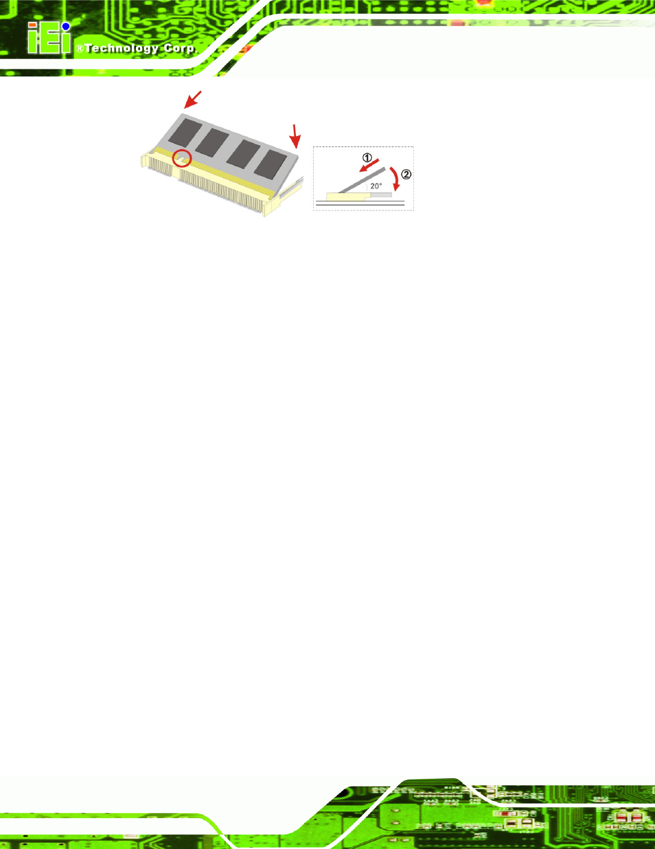
Figure 4-1: SO-DIMM Installation
Step 1:
Locate the SO-DIMM socket. Place the board on an anti-static mat.
Step 2:
Align the SO-DIMM with the socket. Align the notch on the memory with the
notch on the memory socket.
Step 3:
Insert the SO-DIMM. Push the memory in at a 20º angle. (See Figure 4-1)
Step 4:
Seat the SO-DIMM. Gently push downwards and the arms clip into place. (See
4.5 CompactFlash® Card Installation
A CompactFlash® Type II (CF Type II) card slot is located on the solder side of the CPU
board. When appropriately formatted, a CF Type II card can serve as a bootable hard
drive in applications where installation space is limited. The CF Type II card occupies a
secondary IDE channel. Configuration options can be found through the BIOS
configuration utility.
To install a CF Type II card, follow the instructions below.
Step 1:
Turn the CPU board over so that the CF Type II card socket is facing up.
Step 2:
Gently push the CF Type II card into the socket until it clicks into place. (See