2 peripheral interface connectors, Table 3–1: internal peripheral connectors – IEI Integration PM-PV-N4551_D5251 User Manual
Page 29
PM-PV-D4251/N4551/D5251 User Manual
Page 17
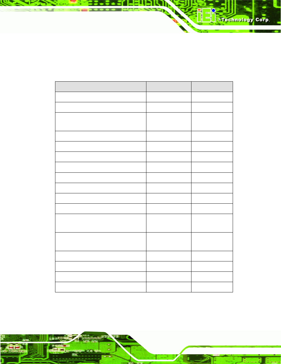
3.1.2 Peripheral Interface Connectors
The table below shows a list of the peripheral interface connectors on the
PM-PV-D4251/N4551/D5251. Detailed descriptions of these connectors can be found in
the following section.
Connector
Type
Label
ATX Power Control Connector
3-pin wafer
ATXCTL1
Audio Kit Connector
9-pin header
J_AUDIO1
CompactFlash® Slot
CompactFlash®
card slot
CF1
Digital I/O Connector
10-pin header
DIO1
Fan Connector
3-pin wafer
CPU_FAN1
Front Panel Connector
10-pin header
F_PANEL1
Keyboard/Mouse Connector
6-pin wafer
KB_MS1
LAN Connector
14-pin header
LAN1
LVDS LCD Connector
20-pin crimp
LVDS1
LVDS Backlight Inverter Connector
5-pin wafer
INVERTER1
PCI-104 Connector
PCI-104 connector
PC104_PLUS1
Power Connector
3-pin terminal block
connector
PWR1
SATA Drive Connectors
7-pin SATA drive
connectors
SATA1
Serial Port Connector (RS-232)
10-pin header
COM1
Serial Port Connector (RS-232/422/485)
14-pin header
COM2
USB Connector
8-pin header
USB01, USB23
VGA Connector
10-pin header
VGA1
Table 3–1: Internal Peripheral Connectors