12 power connector, Figure 3-14: power connector location, Table 3-12: pci-104 connector pinouts – IEI Integration PM-PV-N4551_D5251 User Manual
Page 41: See table 3-12
PM-PV-D4251/N4551/D5251 User Manual
Page 29
Pin
Row A
Row B
Row C
Row D
20
GND AD26 AD25 GND
21
AD29 +5
V AD28 AD27
22 +5
V AD30 GND
AD31
23 REQ0# GND
REQ1# VI/O2
24 GND
REQ2# +5
V GNT0#
25 GNT1# VI/O3 GNT2# GND
26 +5
V CLK0 GND
CLK1
27
CLK2 +5
V CLK3 GND
28 GND
INTD# +5
V RST#
29 +12
V INTA# INTB# INTC#
30
-12 V
TBD2
TBD
GND/3.3 V
Table 3-12: PCI-104 Connector Pinouts
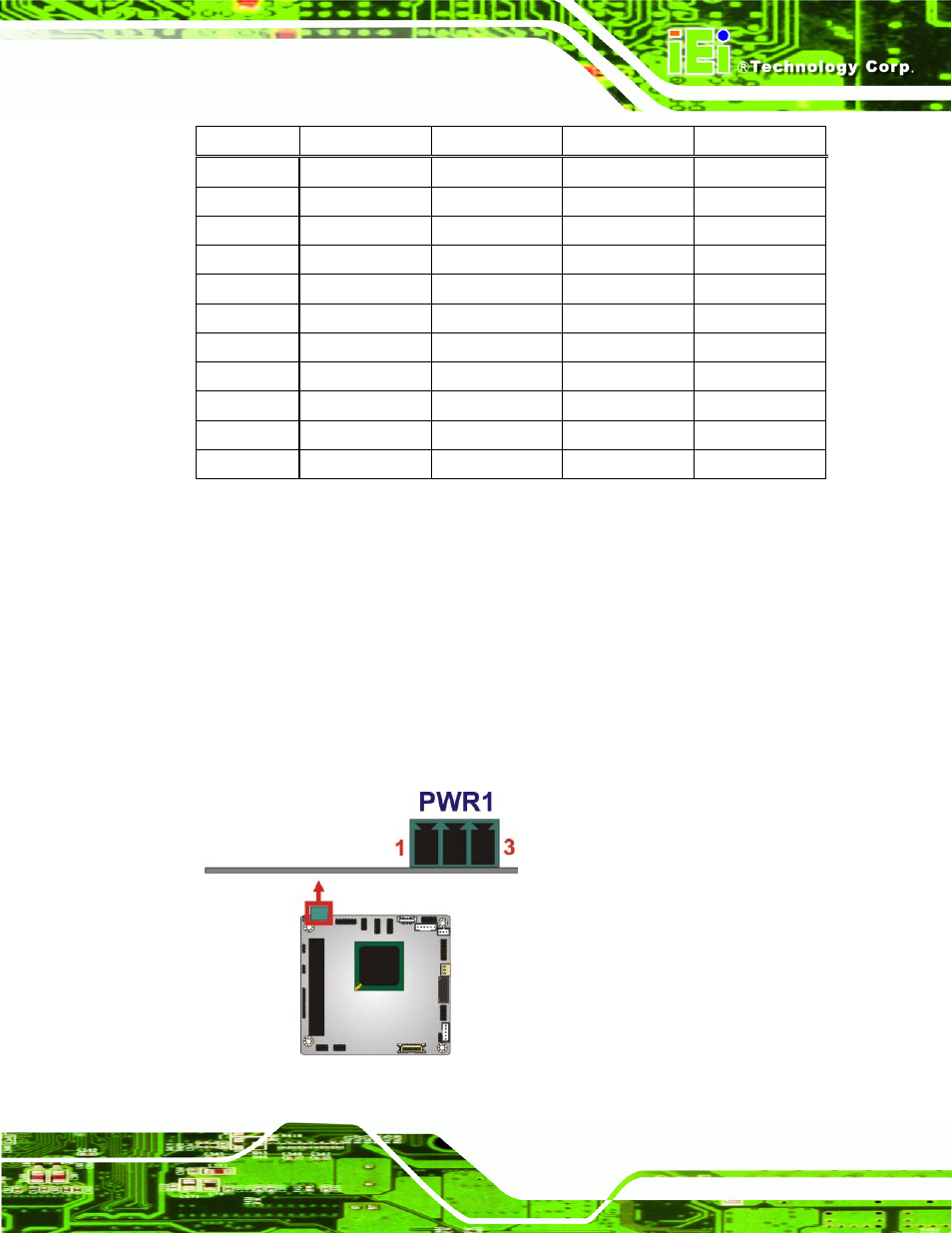
3.2.12 Power Connector
CN Label:
PWR1
CN Type:
3-pin terminal block connector
CN Location:
CN Pinouts:
The PWR1 connector connects to the power source.
Figure 3-14: Power Connector Location
See also other documents in the category IEI Integration Hardware:
- SPCIE-5100DX (180 pages)
- SPCIE-C2060 v1.01 (200 pages)
- SPCIE-C2060 v2.12 (212 pages)
- SPCIE-C2160 (204 pages)
- SPCIE-C2260-i2 (217 pages)
- ROCKY-3786 v4.0 (175 pages)
- ROCKY-3786 v4.10 (147 pages)
- PCIE-Q350 v1.00 (272 pages)
- PCIE-Q350 v1.12 (250 pages)
- PCIE-Q350 v1.20 (250 pages)
- PCIE-Q350 v1.30 (213 pages)
- PCIE-Q57A (159 pages)
- PCIE-G41A2 (151 pages)
- PCIE-Q670 v1.03 (206 pages)
- PCIE-Q670 v2.00 (205 pages)
- PCIE-H610 (181 pages)
- PCIE-Q870-i2 (217 pages)
- IOWA-LX-600 (159 pages)
- PCISA-945GSE v1.01 (207 pages)
- PCISA-945GSE v1.10 (190 pages)
- PCISA-9652 v1.00 (232 pages)
- PCISA-9652 v1.01 (232 pages)
- PCISA-PV-D4251_N4551_D5251 (145 pages)
- PICOe-945GSE (197 pages)
- PICOe-GM45A (198 pages)
- PICOe-PV-D4251_N4551_D5251 v1.00 (154 pages)
- PICOe-PV-D4251_N4551_D5251 v1.10 (154 pages)
- PICOe-PV-D4251_N4551_D5251 v1.11 (155 pages)
- PICOe-B650 (156 pages)
- PICOe-HM650 (174 pages)
- HYPER-KBN (139 pages)
- SPXE-14S (3 pages)
- SPXE-9S v1.00 (5 pages)
- SPXE-9S v1.1 (6 pages)
- SPE-9S v1.00 (4 pages)
- SPE-9S v1.1 (5 pages)
- SPE-6S (3 pages)
- SPE-4S (4 pages)
- PE-6SD3 (4 pages)
- PE-6SD2 v4.0 (4 pages)
- PE-6SD2 v2.10 (3 pages)
- PE-6SD (3 pages)
- PE-6S3 v1.0 (2 pages)
- PE-6S3 v4.0 (4 pages)
- PE-6S2 (4 pages)