3 so-dimm installation, So-dimm, Nstallation – IEI Integration ICE-CV-D25501_N26001 User Manual
Page 40: Figure 4-1: so-dimm installation
ICE-CV-D25501/N26001 COM Express Module
Page 28
4.3 SO-DIMM Installation
WARNING:
Using incorrectly specified SO-DIMM may cause permanent damage to
the ICE-CV-D25501/N26001. Please make sure the purchased
SO-DIMM complies with the memory specifications of the
ICE-CV-D25501/N26001. SO-DIMM specifications compliant with the
ICE-CV-D25501/N26001 are listed in Chapter 1.
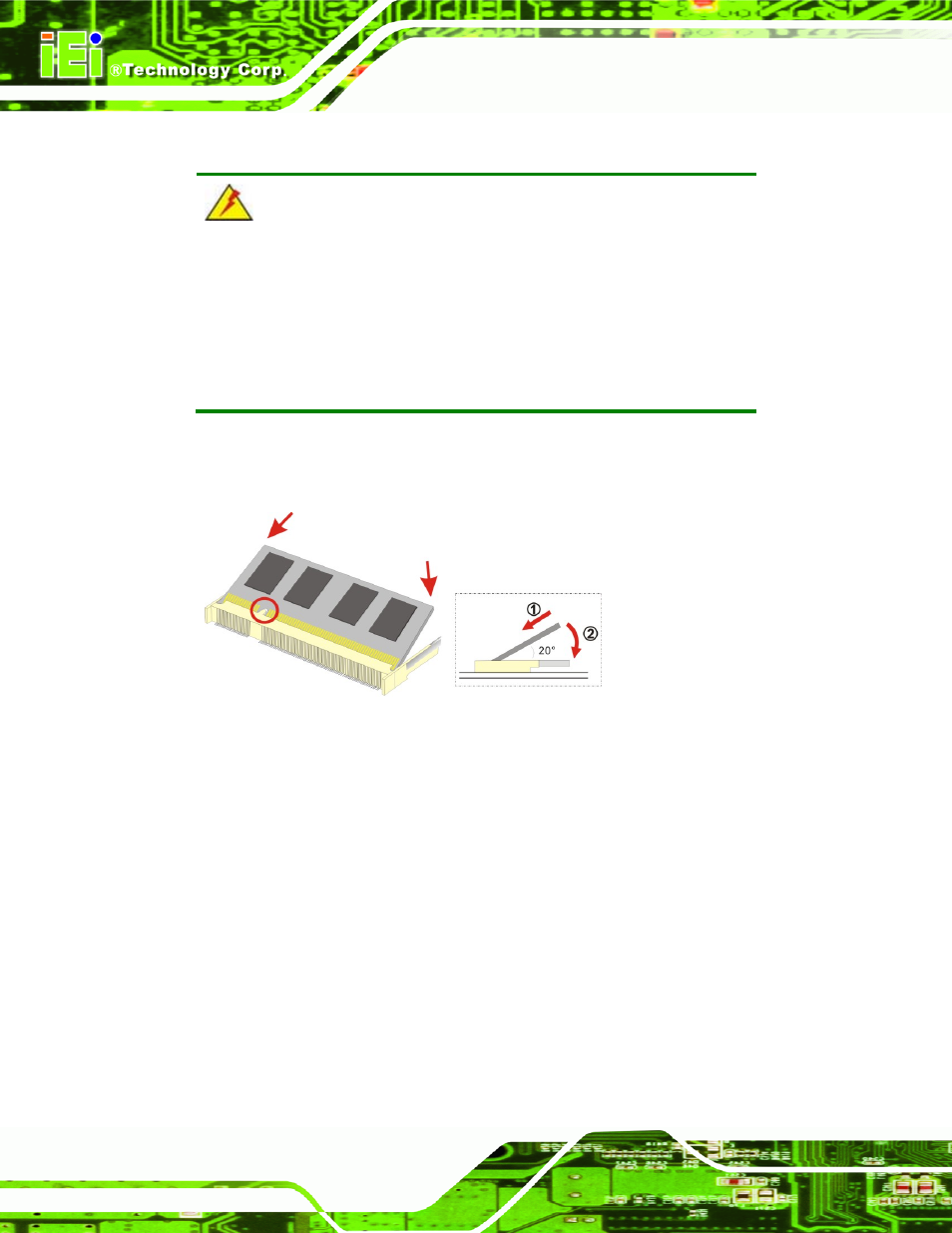
To install a SO-DIMM into a SO-DIMM socket, please follow the steps below and refer to
Figure 4-1: SO-DIMM Installation
Step 1:
Locate the SO-DIMM socket. Place the ICE-CV-D25501/N26001 on an
anti-static pad with the solder side facing up.
Step 2:
Align the SO-DIMM with the socket. The SO-DIMM must be oriented in such a
way that the notch in the middle of the SO-DIMM must be aligned with the
plastic bridge in the socket.
Step 3:
Insert the SO-DIMM. Push the SO-DIMM chip into the socket at an angle. (See
Step 4:
Open the SO-DIMM socket arms. Gently pull the arms of the SO-DIMM socket
out and push the rear of the SO-DIMM down. (See Figure 4-1)