Mounting and installation – Warner Electric CB Series and Super CB Series CB-4 to CB-10 User Manual
Page 2
2
Warner Electric
•
800-825-9050
P-1302
•
819-0447
Warner Electric wrap spring clutches and
clutch/brakes are factory assembled, requiring
no adjustments during installation.
Failure to follow these
instructions may result in product damage,
equipment damage, and serious or fatal
injury to personnel.
Pre-Installation Inspection
Examine the unit for any damage, which may have
occurred during shipping. Check the unit to insure it
meets your application’s requirements, such as
shaft fit and coil voltage. In addition, make sure all
parts are clean and free of any foreign material prior
to assembly.
Mounting and Installation
Whenever attempting to install this
type of product used for engaging and stopping
components on a machine, it is strongly
recommended that the machine be put in a safe
condition prior to servicing.
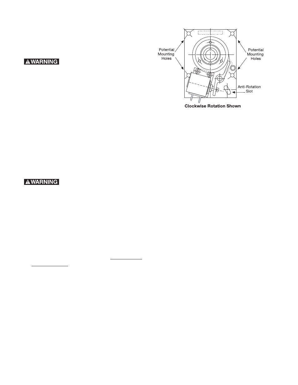
1. Each clutch/brake backing plate assembly
has three or four mounting holes plus an
anti-rotation slot, and is designed to serve as
a torque arm rather than as a rigid mounting
plate. The plate should be restrained from
rotating by a pin or shoulder bolt, while allowing
it to float axially. The anti-rotation device must be
capable of withstanding the braking torque
required by the load.
IMPORTANT: Do not rigidly mount unit. Plate
must be allowed to “float” axially.
2. On CB type units, the input rotation is always
connected to the input hub, and the output is
always through the shaft through the hollow
bore of the clutch/brake.
3. All Warner Electric wrap spring products
are designed to be installed in parallel shaft
applications where they are fully supported by
the shaft on which they are mounted.
Connecting the unit to the parallel shaft may be
accomplished by pinning (for sizes 2, 4, and 5)
or by key and set screw (for sizes 6, 8 and 10).
4. When connecting the parallel shaft to the CB
by using a belt, chain or gear drive, the input
hub’s radial bearing load capacity must not be
exceeded. (See chart below). It may be
necessary to counter bore or bearing mount
the input pulley sprocket or gear.
Maximum Radial Bearing Load at
Maximum Speed
CB-2 = 7.5 lbs.
CB-4 = 14 lbs.
CB-5/Super CB-5 = 32 lbs.
CB-6/Super CB-6 = 63 lbs.
CB-8/Super CB-8 = 300 lbs.
CB-10/Super CB-10= 500 lbs.
+
+
+
+
+
+
+
+
+
+
+