The electrical system, Type "k" dc lvdt, Figure 3 – Warner Electric C30 Single Range Tensioncells User Manual
Page 4
4
Warner Electric • 800-825-9050
P-2012-5
For our discussion here, deflection of the Load
Plate toward the Base Block is defined as the
"Compression Mode", while the opposite is
defined as the "Tension Mode". Tensioncells are
designed to operate equally well in either mode.
The Base Block contains an integral Mechanical
Stop to limit the amount of deflection in either
direction, and a Viscous Damper to allow
control of the tensioncell response to rapid
changes in apparent tension loads. (See Page 3,
Figure 2)
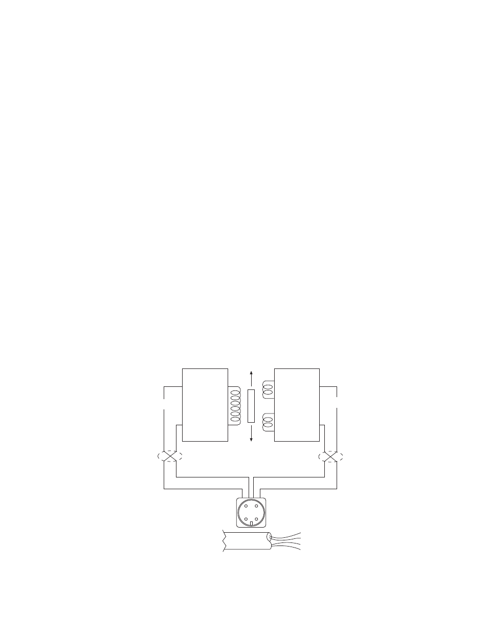
The Electrical System
The electrical system consists of a Linear
Variable Differential Transformer (LVDT) which
converts the mechanical deflection of the Load
Plate into a useful electrical output signal. (See
Figure 2) The movable core of the LVDT is
mechanically coupled to the Load Plate by
means of the Core Adjust Assembly. (See Figure
3) This adjustment is factory set and is not
accessible.
Black - (2)
Red + (1)
Green (3)
Blue (4)
Input
Output
X Twisted Leads
A B
Oscillator
Demodulator
P1
S1
S2
X
X
When
Su
pp
lied
wi
thCable
(1)
Red
+
DC
(2)
Black
–DC
(3)
Green
–Signal
(4)
White
+
Signal
CD
B
A
C
D
Figure 3
Type "K" DC LVDT
As illustrated in Figure 4, a DC LVDT consists
of the following components:
• An oscillator network, which converts the
DC input voltage into a high frequency alter-
nating current for exciting the primary coil
(P1).
• A Primary Coil (P1)
• A movable, permeable metallic core
• Two Secondary Coils (S1 and S2)
• A demodulator and summing network to
rectify and integrate the currents from the
Secondary Coils