Description general information, The mechanical system – Warner Electric C30 Single Range Tensioncells User Manual
Page 3
3
Warner Electric • 800-825-9050
P-2012-4
Description
General Information
Warner Electric Series 30 Type C Tensioncells
are force transducers especially designed to
measure and control web tension on continuous
strip processing lines. They are normally
installed in matched pairs at each end of a
measuring roll. (See Figure 1)
A Tensioncell consists of a unique combination
of two integral systems (one mechanical, the
other electrical) for converting the mechanical
force of strip tension into an electrical signal
which is directly proportional to the strip ten-
sion.
Type "C" Tensioncells are intended for ROTAT-
ING shaft installations. They are supplied with
self-aligning ball bearings to assure positive
alignment of the measuring roll. Type "C"
Tensioncells are supplied in matched pairs, one
to be mounted at each end of the tension meas-
uring roll. Note that the cell marked "W2" is a
mirror image of "W1". The 'W2" cell allows for
thermal expansion of the rotating shaft. (See
Figure 1)
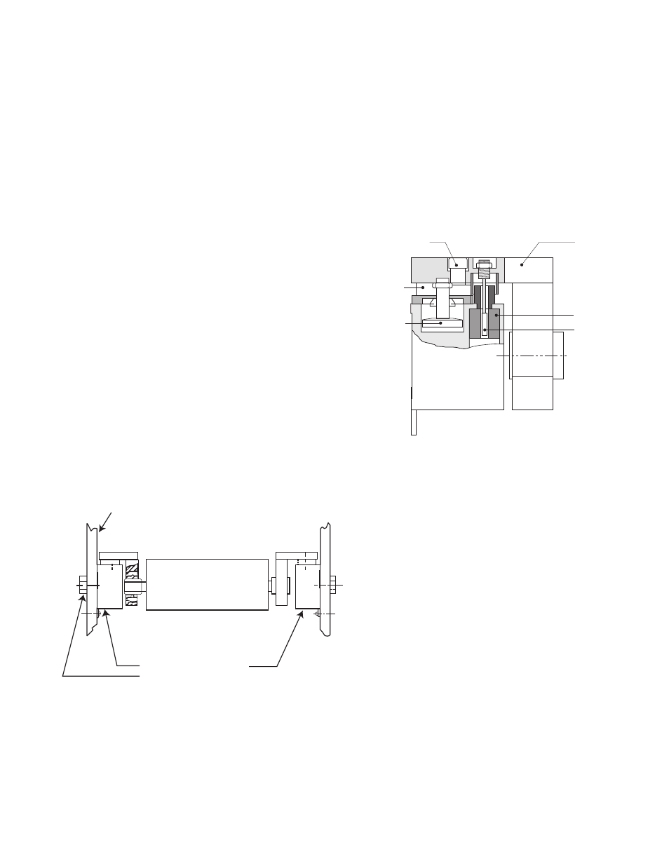
W1
W2
Machine
Frame
C30 Series Tensioncell
Single Bolt Mounting
Self-Aligning Bearings in Tensioncell - Rotating Shaft
Figure 1
Damper
C-Flexure
Far Side
Mechanical Stop
Load
Plate
LVDT
LVDT
Core
Figure 2
The Mechanical System
The mechanical system consists of a Patented
"C-Flexure Pivot Assembly" which incorporates
a mounting Base Block, frictionless elastic pivot
(or hinge), and Load Plate. (See Figure 2) When
a mechanical force is applied to the Load Plate,
the pivot permits its deflection toward or away
from the Base Block.