Wiring hookup, System example – Warner Electric FM Series Foot Mounted Load Cells User Manual
Page 4
4
Warner Electric • 800-825-9050
P-2012-1
Wiring Hookup:
The load cell requires a +15VDC and a -15VDC
power supply. The 5V/15V switch inside the
MCS2000-CTLC must set to +/-15VDC.
Terminate all unused wires from cable.
Wiring example using One Load Cell with the
MCS2000-CTLC control
Red (+15V)
White (Ground)
Yellow (Signal)
BLUE (-15V)
+UCELL/SEN+
CELL1+/SENS IN
CELL1-
-UCELL/SENS
Ground (OV)
Shield
+UCELL
CELL2+
CELL2-
-UCELL
SHIELD
FM Series Load Cell
MCS2000-CTLC
No Connection
No Connection
No Connection
No Connection
Add Jumper
Red (+15V)
White (Ground)
Yellow (Signal)
Blue (-15V)
+UCELL/SEN+
CELL1+/SENS IN
CELL1-
-UCELL/SENS
Ground (OV)
Shield
+UCELL
CELL2+
CELL2-
-UCELL
Ground (OV)
Shield
Red (+15V)
White (Ground)
Yellow (Signal)
Blue (-15V)
N/C
N/C
FM Series Load Cell
FM Series Load Cell
MCS2000-CTLC
Figure 2
Figure 3
Wiring example using 2 load cells with the
MCS2000-CTLC control
Notes:
It is recommended to use the load cell
in a compression application. It must be fitted
on a flat surface in order to avoid original
sensitive plate stress. Do not load the sensor
before mounting it with screws on the
mounting surface.
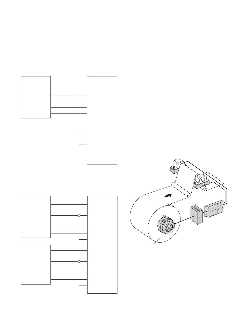
System Example:
FM Load Cell with an Electric Brake
This is a typical load cell unwind application
example. The electric brake varies the tension
on the web depending on the feedback from the
load cell. The load cell signal is amplified and
interpreted in the controller (MCS2000-CTLC).
The controller then puts out a corresponding
0-10 VDC signal to the power supply and drive
(MCS2000-PSDRV). The PSDRV then amplifies
and interprets the signal from the controller and
puts out a corresponding 0-24 VDC signal to the
brake to apply either more or less braking.
Figure 4
Magnetic Particle Brake
MCS2000-PSDRV
Power Supply
and Drive
MCS2000-
CTLC
FM Load
Cell
FM Load
Cell