Warner Electric FM Series Foot Mounted Load Cells User Manual
Page 3
Model Numbers/Part Numbers
FM01-100
6910-840-100
FM01-250
6910-840-102
FM01-500
6910-840-104
FM01-1000
6910-840-106
FM01-2500
6910-840-108
FM01-5000
6910-840-110
FM01-10K
6910-840-112
3
Warner Electric • 800-825-9050
P-2012-1
The FM style load cell provides easy and conven-
ient mounting to the roll that is being measured
(used with pillow blocks). The load cell is a strain
gauge style unit that is ideal for heavy tension
applications. It can be mounted regardless of ori-
entation, but has to work in compression. Only
the perpendicular force (resultant) is measured by
the load cell. The perpendicular force can be at a
maximum permitted angle of +/- 30 degrees.
Correct load cell sizing must be adhered to so
potential overload forces do not damage cells.
Specifications:
Load
Ratings
N
100 250
500 1000 2500 5000 10000
(Lbs.)
(22) (56) (112) (225) (562) (1124) (2248)
Size
01
01
01
01
01
01
02
Input Power
±12 to ±15 VDC
@ 45 MA ±5%
Output Signal
5VDC output at rated load
Temperature Range
0-70 degrees C
(32 -158 degree F)
Temperature drift
0.1 % of rating per degree C
Non-linearity and Repeatability
< 0.5%
Power Consumption
1 Watt
Cable
16 ft. provided with load cell
Maximum Load Ratings (See Figure 6)
Overload
120% of rated load
Compression Overload
150% of rated load
Horizontal Load
50% of rated load
FM Series Part Numbers
F M
0 1
-
1 0 0 0
-
A C
Model Size Load in N Amplifier built in
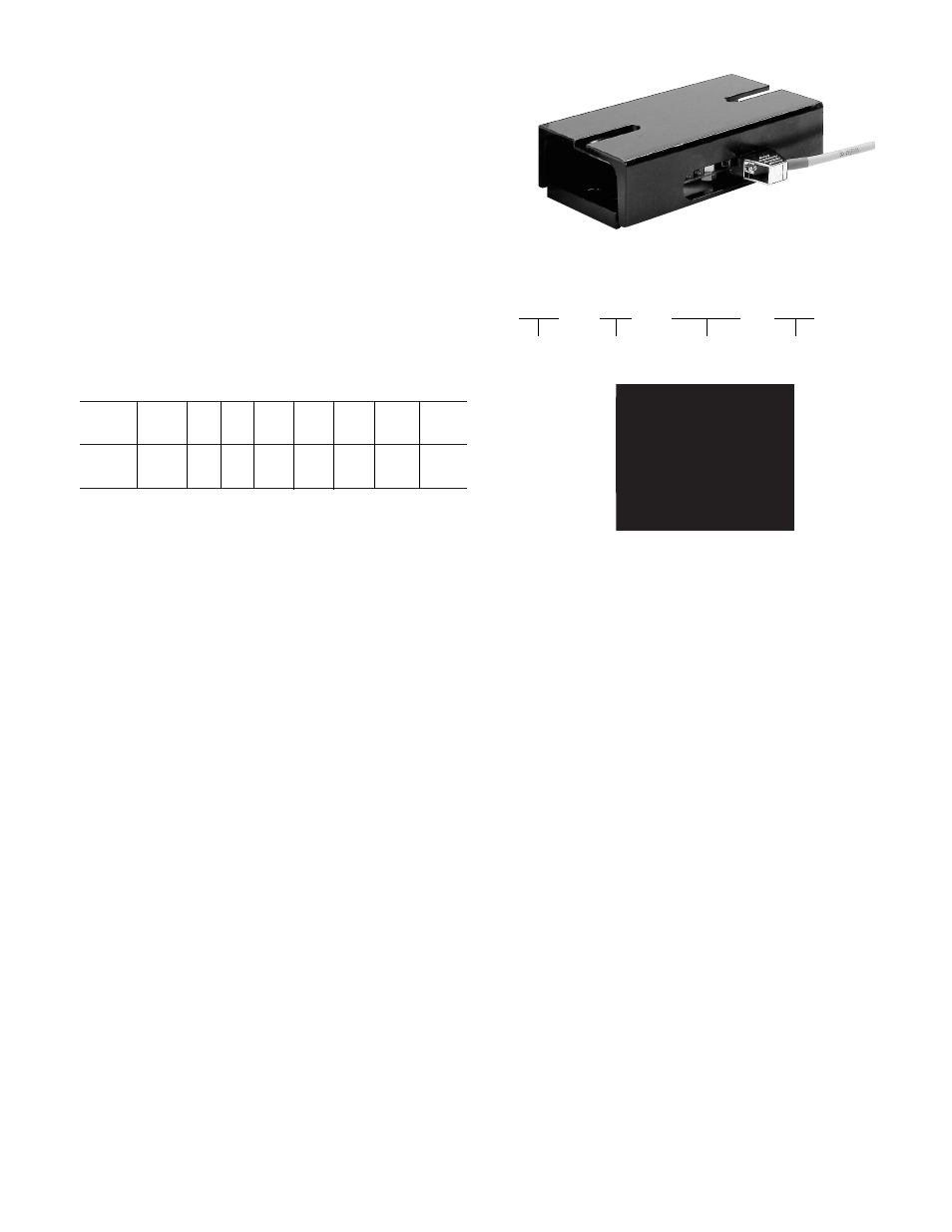
Alignment
Zero setting:
Green LED ON
above 0 VDC
Gain setting:
Green LED ON
below 5 VDC
Green LED
D-Sub connector
The sensor has been factory calibrated:
0VDC (No load)
5VDC (Rated load)
Two potentiometers and LED’s are located near
the “D” connector (See Figure 1) for visual indi-
cation. When used in the nominal range, both
LED’s are “ON”. Although the load cell has been
factory calibrated. The unit may be rescaled if
necessary. It is recommended that a qualified
technician do this procedure.
Attach a digital volt meter between the signal
lead (yellow) and 0VDC (ground). With no load
on the cell adjust the zero potentiometer for a
0VDC output. The zero setting LED should be
“OFF”. Any voltage above 0VDC, the zero LED
will turn “ON”.
Apply the mazimum load to the cell. Adjust the
gain potentiometer for a 5VDC output reading.
The gain LED should be “OFF” at a 5VDC output
level. Remove the load and insure the gain LED
is “ON”.
The zero and gain adjustments may need to be
repeated a couple of times to insure proper set-
ting.
Figure 1