Warner Electric Safety Interlock Switch User Manual
Page 3
3
Warner Electric • 800-451-8279
P-1488 • 819-0467
Warner Electric • 800-451-8279
P- 1488 • 819-0467
22
8
A
B
1
3
4
2
180°
52
90
18
29
8
40
7
27
30
15
40
11
23
12
24
3.4
3,2
2,4
20.5
mm
Actator
Extended
Retracted
On
Off
11
-12
23-24
52
40
R min. 150
R min. 150
22
50
16
6
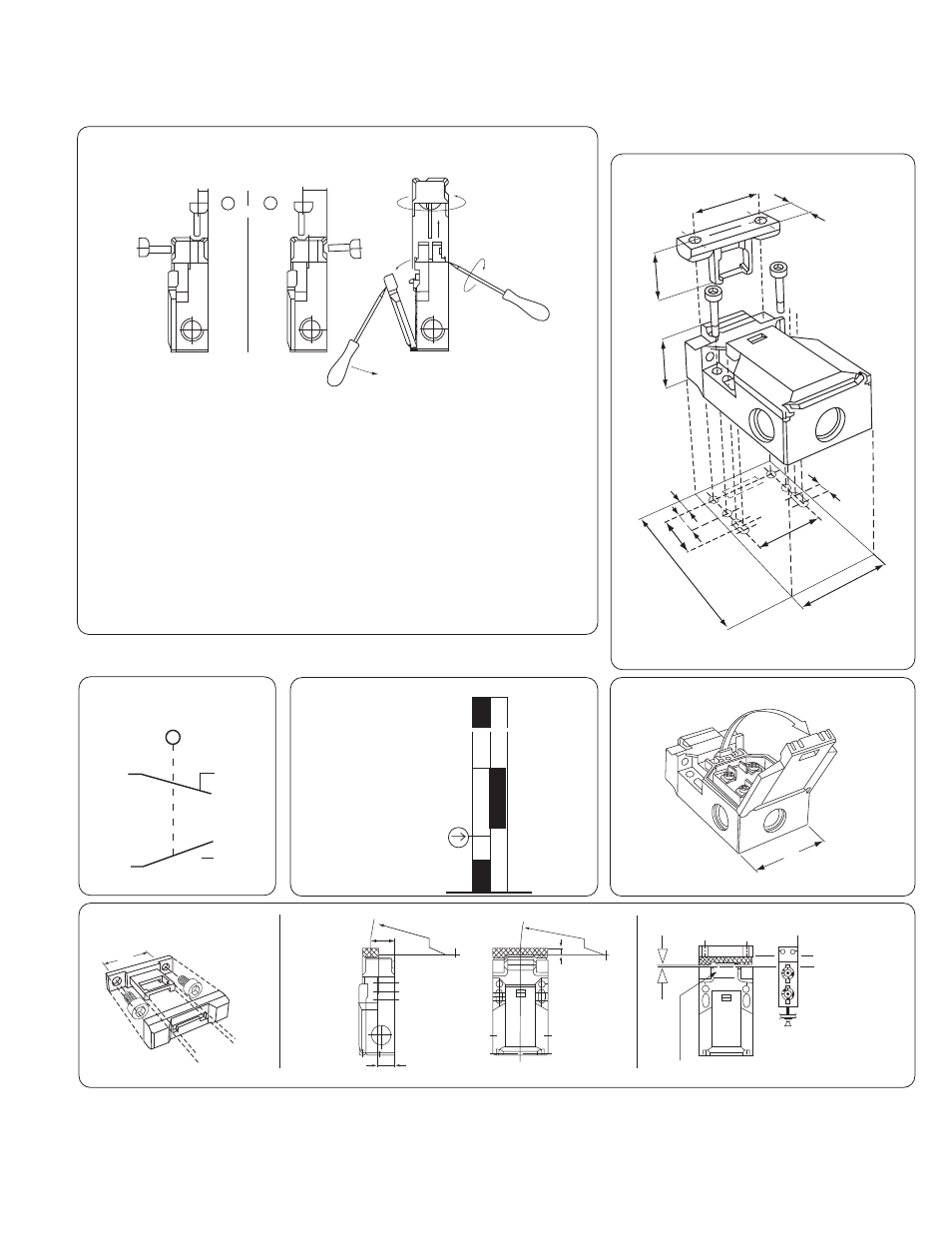
Don't use the switch as stop.
• 4 approach directions by changing the cap’s position A or B.
• Cover 1 has to be opened before changing cap 2.
• Insert the screwdriver point into the separable gap housing and
rotate screwdriver (until the cap unlocks) 3.
• Remove the cap and according to picture 4 turn around 180°, to put
into housing and close the cover to lock cap.
• Radial actuation will reduce the mechanical life of the switch.
Observe the minimum radius as shown in the Actuator Mounting
directions.
• Unused key slots covered with plastic insert.
Actuation Directions
Contact
Operation
Switching Diagram
Threaded Entrance Holes M20
Threads
Mechanical/Dimensions mm
mm x .0394 = inches
Actuator Mounting
Supplied with 1/2” NPT Conduit Adaptor
- UNIBRAKE NEMA 4 (6 pages)
- UNIBRAKE (8 pages)
- ARC 2000 (16 pages)
- ARC Clutch_ZRC Top Load (18 pages)
- ZRC Clutch_ARC Top Load (18 pages)
- Dairy Cap Chuck (24 pages)
- Dairy Capping Headsets (10 pages)
- Autogap 475 & 650 (4 pages)
- Brushholder Installation (2 pages)
- Autogap 825-1225 (2 pages)
- Electro-Packs EP-170, 250, 400, 500, 825, 1000, 1525 (20 pages)
- Electro-Brake 375, 475, 650, 825, 1000, 1225 (20 pages)
- Electro-Clutch EC-375, EC-475, EC-650, EC-825, EC-1000, EC-1225 (20 pages)
- 5300-101-001 Collector Ring (2 pages)
- 5301-101-010 Collector Ring (2 pages)
- Brushholder Assembly and Mounting Dimensions (2 pages)
- SF_PB 400 (2 pages)
- SF_PB 250 (2 pages)
- Autogap 825-1525 (4 pages)
- Electro-Module EM-50, EM-100, EM-180, EM-210, EM-215 (22 pages)
- FB-375, 475, 650 (14 pages)
- 5200-101-012 Conduit Box Kit (4 pages)
- 5200-101-011 Conduit Box Kit (4 pages)
- 5200-101-010 Conduit Box Kit (4 pages)
- Recommended Electrical Installation Procedure for Warner Electric Clutches and Brakes (2 pages)
- EP-400 Vertical Mounting (2 pages)
- EP-250 Vertical Mounting (2 pages)
- Autogap 500 (4 pages)
- ER 825 and 1225 Normal Duty (16 pages)
- ER 825 and 1225 Heavy Duty (14 pages)
- ERS Electrically Released Brakes (6 pages)
- AT Brakes & Clutches Complete Brake Repair – On the Shaft, Sizes 25, 55, 115 (4 pages)
- AT Brakes (6 pages)
- AT Brake–Major Service Repair Instructions for Sizes 25, 55, 115 (9 pages)
- AT Clutch – Major Service Sizes 25, 55, 115 (12 pages)
- 5162-101-002 Conduit Box Kit (6 pages)
- Electrically Released Permanent Magnet Clutch Compatible Modules (4 pages)
- Electrically Released Motor Brake Module for EM-MBFB and EUM-MBFB (6 pages)
- Electrically Released Brake Module For EM-FBB and EUM-FBB (4 pages)
- Electrically Released Brake ER-375, ER-475, ER-650 (12 pages)
- Autogap 825-1525 Special Heavy Duty (4 pages)
- 5370-101-042 Conduit Box Kit (4 pages)
- Preassembled Clutch_Electrically Released Brake Module (7 pages)
- EUM-50_EUM-100_EUM-180_EUM-210_EUM-215 (16 pages)
- 5370-101-045 Conduit Box Kit (5 pages)