Warner Electric Safety Interlock Switch User Manual
Page 2
Contents
Description . . . . . . . . . . . . . . . . . . . . . . . . . . . . 2
Features . . . . . . . . . . . . . . . . . . . . . . . . . . . . . . 2
Mechanical Features . . . . . . . . . . . . . . . . . . . . . 2
Electrical Features. . . . . . . . . . . . . . . . . . . . . . . 6
Actuation Directions . . . . . . . . . . . . . . . . . . . . . 3
Mechanical/Dimensions . . . . . . . . . . . . . . . . . . 3
Switching Diagram . . . . . . . . . . . . . . . . . . . . . . 3
Contact Operation . . . . . . . . . . . . . . . . . . . . . . 3
Threaded entrance Holes . . . . . . . . . . . . . . . . . 3
Actuator Mounting . . . . . . . . . . . . . . . . . . . . . . 3
Warranty . . . . . . . . . . . . . . . . . . . . . . Back Page
Failure to follow these
instructions may result in product
damage, equipment damage, and
serious or fatal injury to personnel.
2
Warner Electric • 800-451-8279
P- 1488 • 819-0467
Description
Safety Switch with positive opening normally
closed contacts which can only be activated with a
specially designed mating key that protects against
unintended operation.
Features
• Easy installation
• Actuator head can be oriented to 4 different
approach directions quickly and easily
• Positive opening of the normally closed
contacts for safety
• UL listed
• NEMA-4 rating
• Easy wiring access
• 3 cable entry holes with M20X1.5 threads
• 1/2” NPT conduit adaptor supplied with switch -
part # 104-8001-004
• Strain relief adaptors are available to order -
part # 280-8035-002
Enclosure:
Thermoplastic,
glass fiber reinforced
Actuator:
Separate Actuator,
Aluminum (M5 dia.
mounting holes) with
plastic snap cover
Switch
2 x M5 round and
Mounting:
2 x M5 elongated
holes
Operational
-30°C/+80°C
Temperature:
-22°F/+176°F
Contact
1 N.O. - 1 N.C. with
Type:
forced disconnect of
N.C. contacts
Mechanical
1 million switch
Life:
operations
Protection:
IP 65/Nema 4
Termination:
4 screw terminal
connections M3.5
Screws
Rated voltage: = 500V AC Max
Rated current:
= 10 A max.
sustained current
CSA:
10A, 300VAC,
A300, Same
polarity
Utilization Categories per
IEC 945-5-1,
AC = 15
DC = 13
VDE 0113
VDE 0660 Part 200
IEC 947-5-1
GS-ET 15
APPROVALS
STANDARDS
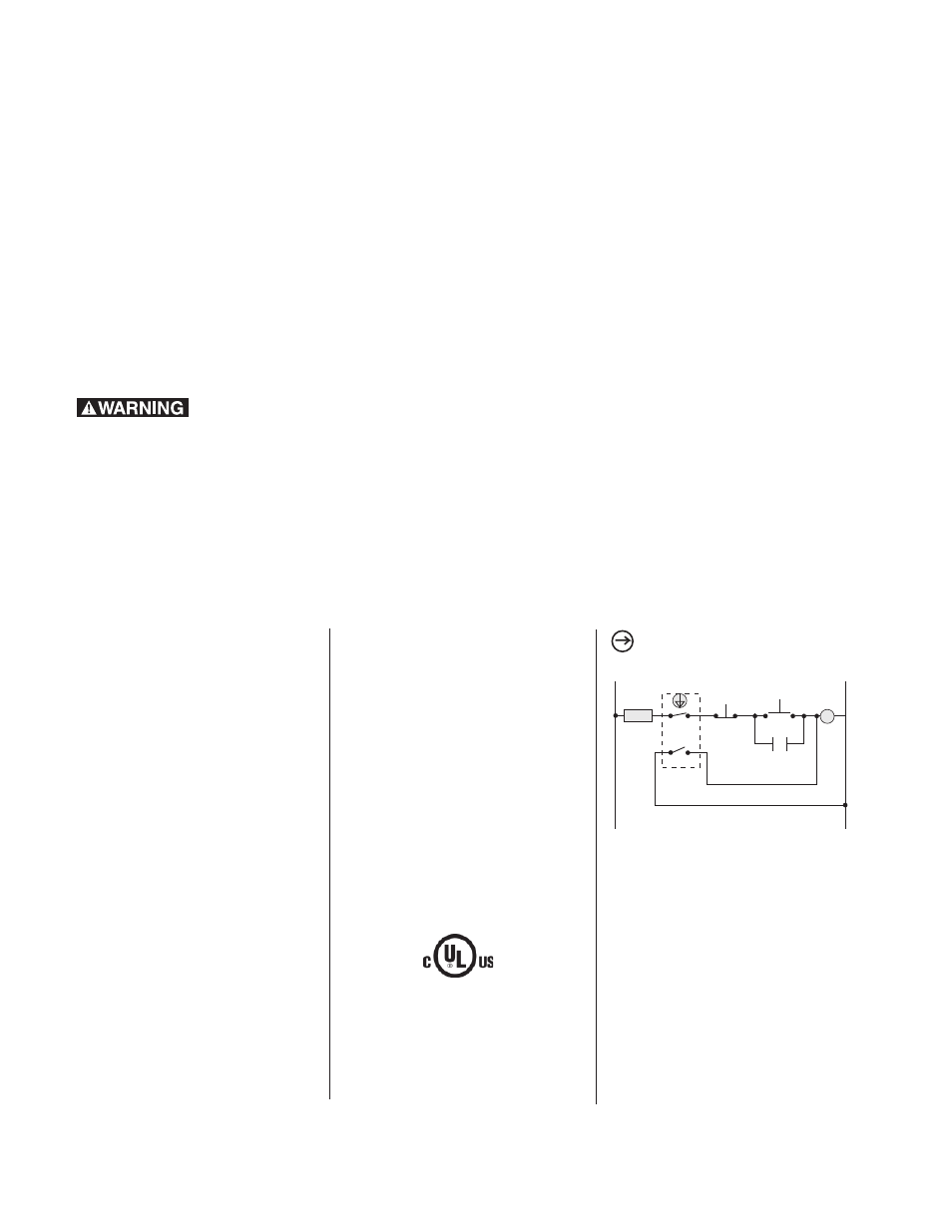
FUSE
M
M
24
23
11 12
L1
L2
START
STOP
SAFETY SWITCH CONTACTS
WITH KEY INSTALLED.
Special wiring for the safety-interlock
switch to prevent tampering. The N.O
contact 23-24 short circuits the coil of
motor starter (M) with key removed. If the
N.C. contact 11-12 were jumpered, the
fuse would blow when the key is removed
from the switch and an attempt is made to
restart the circuit.
NOTE: Fuse to be 10 Amp slow acting or
16 Amp fast acting type.
MECHANICAL FEATURES
ELECTRICAL FEATURES