Warner Electric Heavy Duty Industrial Foot Switches User Manual
Page 2
2
Warner Electric • 800-825-9050
P-1303 • 819-0523
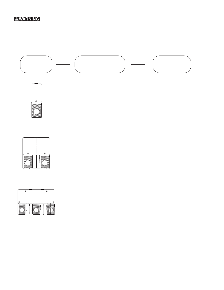
Explanation of Model Identification
Code for Foot Switches
Number of
Pedals
Contact Block
Function
Additional
Features
F1 = One Pedal Foot Switch
F2 = Two Pedal Foot Switch
F3 = Three Pedal Foot Switch
U1 =
Slow Action
1 NO / 1NC Single
Pole Break Before
Make Momentary
SU1 =
Snap Action
1NO / 1NC Single
Pole Momentary
U2 =
Slow Action
2 NO / 2 NC Double
Pole Break Before
Make Momentary
SU2 =
Snap Action
2 NO / 2NC Double
Pole Momentary
NO = Normally Open
NC = Normally Closed
Z =
(example U1Z) indicates a
forced disconnect of the
Normally Closed Contacts.
Y =
(example U1Y) indicates a
maintained contact. 1st
depression of pedal latches switch
on 2nd depression
releases.
D =
(example U2D) indicates a
pressure point for operation
with 2 contact blocks, 2 stage
operation. 1st block operates
up to pressure point, 2nd block
operates after operation of
pressure point switch.
AT =
(example SU1Z AT) indicates an
Anti-Trip Device. A lever must be
pushed forward with a foot before
the pedal can be pressed.
UN =
(example F1-U1Z UN) indicates a
Protective Guard over the pedal.
Mi RG =
(example SU1 Mi RG) indicates a
proportional output, fitted as stan-
dard is a varible resistor,
10K ohms, 2W.
AP =
(example F1-U1 AP) Explosive
proof switch for operation in med-
ical areas “surgically safe”.
Dash
Dash
Failure to follow these instructions may result in product damage, equipment
damage, and serious or fatal injury to personnel.
Multi Pedal Switches:
With multi-pedal switches, it is possible for each pedal to have
its own function. The functions available are explained in the
Contact Block Function area of the Identification Code.