Install brakes, Install armature in drum – Warner Electric Wheel-Brakes (Std) User Manual
Page 8
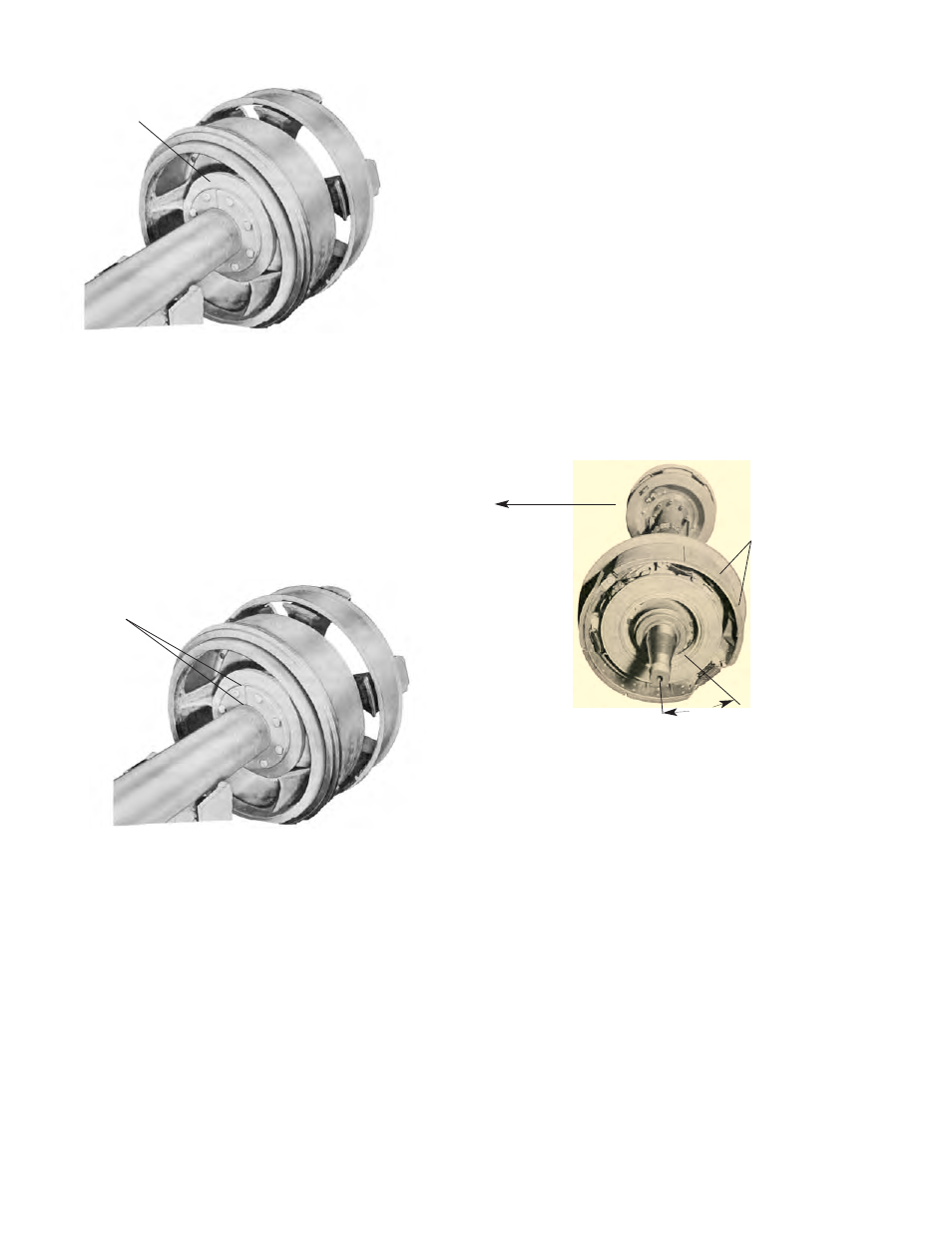
Figure 2-8
Location of Shims for Welding Flange
With an electric arc, tack both outer edges of hacksaw
cut, if cut is present. Tack flange (Figure 2-9) to axle in
approximately four places. Complete weld by welding
hacksaw cut first - outer edge to axle - then make
continuous weld between flange and axle. Remove
bolts that hold flange to welding fixture and remove
hub, drum, and welding fixture from axle. Complete
weld on opposite side of flange. Remove welding
fixture from drum and clean all weld splatter from drum
or spindle surfaces.
NOTE:
Do not use same hub and drum assembly as
template for all wheels. Use hub and drum
designated for each wheel location.
Install Brakes
The desired position for mounting brakes on the axle is
indicated in Figure 2-10. Whenever possible they
should be mounted so that the brake spider anchor is
down and 45° to the rear as determined by forward
vehicle travel. Mounting brakes in this position affords
the best wheel bearing loading during application of
brakes. If the brakes are marked right and left hand
because of the type and location of lining segments in
brake shoes, the woven lining (with arrow indicating
drum rotation for forward vehicle travel) must always
be on the toe end of the shoe ring. Left and right hand
are determined by facing in the direction of forward
vehicle travel. In the event it is not possible to locate
the brake spider anchor as shown, the anchors must
be in the same relative location for all wheels.
Figure 2-10
Brake Mounted in Correct Position
Install Armature in Drum
Bolt armature inside of drum (Figure 2-11). Armature
bolts directly to armature adapter for 16-
1
⁄
2
” series
brakes. On 12-
1
⁄
4
x 5-
1
⁄
2
” and 15 x 3” brakes, grease
guard is placed between armature and drum when
armature is bolted in place. A thin coating of
“Permatex” or other suitable sealer must be used
between grease guard and drum at this time.
8
Warner Electric • 800-825-9050
819-0514
Figure 2-9
Weld Points on Flange
Shims
Tack Weld
Direction
of Travel
For Brakes
Marked Right
and Left Hand
Locate Woven
Lining on
Toe End
Brake
Spider
Anchor
45°