Warner Electric P 130 VAR00_VAR02 User Manual
Page 4
4 Warner Electric Europe • +33 (0)2 41 21 24 24
P-2081-WE • 2/13
4.2
Spare Parts
All orders for spare parts must state the size
of the unit with its code number, the reference
number of the part (see appendice 1), and the
quantity of each component wanted.
4.3
Dismantling / Reassembling
During maintenance work, ensure that the
mechanism to be driven by the clutch is at
rest and that there is no risk of it being started
accidentally. Also ensure that the compressed
air is turned off.
Dismantling:
• Remove the fixing screws from the cylinder
(401) or closing flange (408)
• Remove the cylinder (401) or closing flange
(408)
• Take out the piston (402)
• Remove the worn disc set
• Fit a new disc set
Start with an outer disc (302 or 305), then an
inner disc (308), and then alternate, ending of
necessity with an outer disc.
• Change the seals (701, 702)
• Refit the piston (402)
• Refit the cylinder (401) or closing flange (408)
Take care not to damage the seals while
reassembling
• Replace the cylinder (401) or closing flange
(408 fixing screws, tighten them to the torque
shown in table 3, below and secure them with
Loctite 243 or an equivalent type of product
5
Pneumatic Connections
5.1
Important Recommendations
Ensure that working pressures are complied
with, to get the nominal performance from the
equipment.
Do not exceed the maximum pressures
(see table 1).
These clutches should be supplied with filtered,
oiled air.
5.1
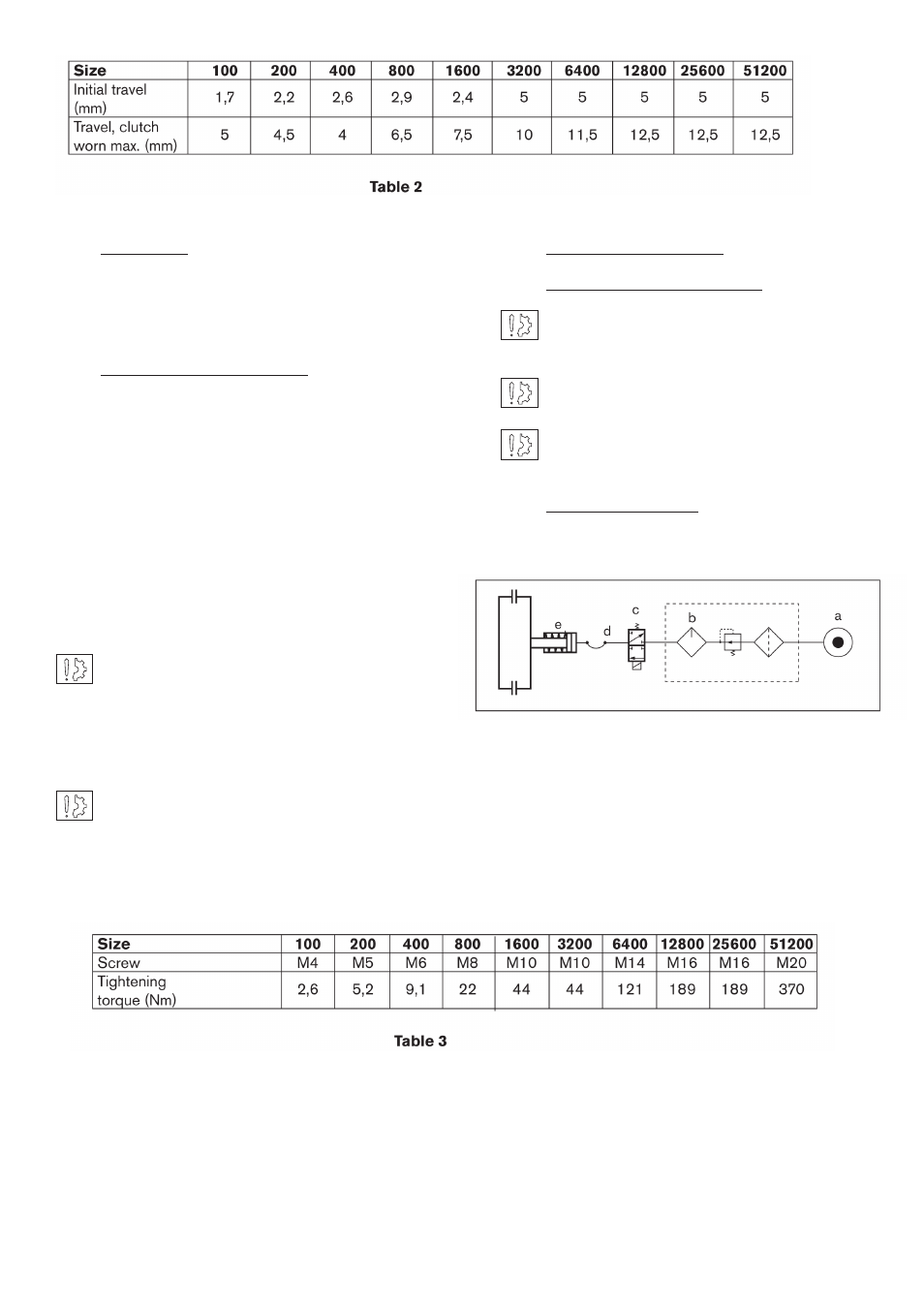
Connection Diagram
The diagrams are only given as an indication.
Fig 1: Basic circuit for circuit under pressure
a: source of pressure
b: air treatment unit
c: distributor
d: flexi pipe and rotating seal
e: clutch engagement by application of pressure