Warner Electric SFM and Brakes PBM Electro-Magnetic Single Disc User Manual
Page 3
Warner Electric Europe • +33 (0)2 41 21 24 24
P-2086-WE • 11/12 3
Fig. 1
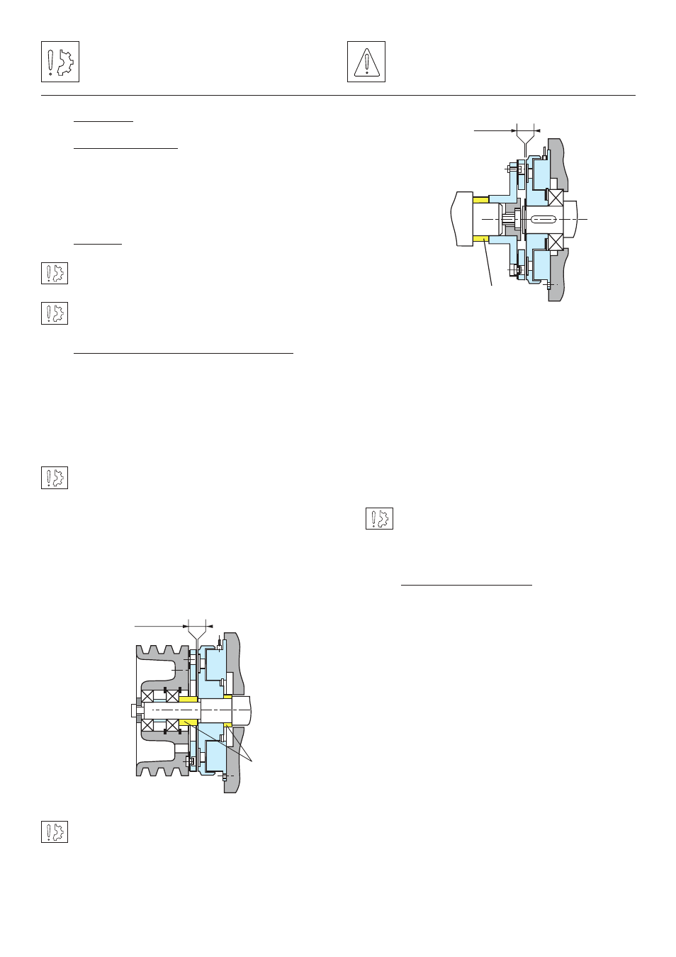
Airgap
Adjusting
spacer
Fig. 2
Airgap
Adjusting spacer
Symbol designating an action that
might damage the apparatus
Symbol designating an action that
might be dangerous to human safety
3
Installation
3.1
Transport / storage
These units are delivered in packaging that
guarantees a 6 months storage period whether
transported by land, by air, or by sea to any
destination excepting tropical countries.
3.2
Handling
Avoid any impacts on the equipment so as not to
alter their performance.
Never carry the equipment by the electrical supply
cable.
3.3
Installation 3.3.1SFM (VAR00 and VAR01)
Inductor (104) should be fixed to the frame of the
machine, centred by the collar (see figure 1) or
directly centred on a bearing forming a support
(see figure 2). In this case, a circlip fitted in the
groove provided for the purpose holds it central to
the bearing.
In the case of collar centring, we specify an H9
tolerance.
The setover between the housing and shaft should
not exceed 0.05 mm.
On VAR00, the armature (331) is fixed by means
of CHC “profile head” screws (DIN 7984) locked
by means of a LOCTITE 270 type thermoplastic
liquid.
In the case where two co-axial shafts are fitted,
the recommended setover is 0.05 mm maximum.
The angular misalignment should not be greater
than 0,1 mm over a length of 100 mm.
On VAR01 the armature is mounted on a hub
(332), sup plied reamed to tolerance H7 and
splined to tolerance P9.
The assembled hub / armature assembly
should be secured centrally so as to respecter
the nominal airgap.
It is essential when assembling to respect the
nominal airgap (see chapter 1) and dimension
M (See table 1).
When assembling or dismantling the moving
armature,
never hit or pull it, this action could
generate permanent distortion of the
membrane-spring and malfunction.
3.3.2 SFM (VAR10 and VAR11)
The inductor (109) is stopped from rotating by
means of a stop foot. This should be fitted so
as to get a minimum play of 0,25 mm between
the sides of the notch to avoid any strain on the
inductor and internal bearing.
In case of vibrations, it is strongly recommended
to insert a damping elastic slot between the
anti-rotation device and the anti-rotation slot
and to fix the coil’s cable the nearest of it to
avoid whipping.
On VAR10, the armature is fixed (331) by means
of CHC “profile head” screws (DIN 7984) locked
by means of a LOCTITE 270 type thermoplastic
liquid.
Fig. 1
Fig. 2
Fig. 1
Airgap
Adjusting
spacer
Fig. 2
Airgap
Adjusting spacer