Warner Electric CB & Super CB Series Wrap Spring Clutches & Brakes User Manual
Page 6
6 Warner Electric Europe • +33 (0)2 41 21 24 24
P-2026-WE • 11/12
8.
Assemble circlip (1) at input hub (2).
9.
If anti-overrun is required : rotate output into STOP position. Remove circlip (1) and input hub (2). Screw
carefully anti-overrun spring (5) into output hub. Assemble input hub (2) by rotating in the direction of
operation. Assemble circlip (1).
10. Check actuator setting (12)
3
SERVICE INFORMATION
3.1 ADJUSTMENT OF THE CONTROL COLLAR
1.
Work retaining ring (A) out of groove and slide
forward on sleeve (C).
2.
Slide stop collar (B) off splines, rotate
to desired stop position and slide back on
splines. The actuator pawl will have to be held
clear during this operation.
3.
Slide retaining ring back (A) into
groove.
Note : make sure brake is
locked up before proceeding to ensure
proper stop position.
Smallest adjustable angle:
CB-2 : 2,8º CB-6 : 1,8º CB-10 : 1,5º
CB-4 : 2,4º CB-7 : 1,6º
CB-5 : 1,8º CB-8 : 1,6º
A
B
C
1.
Loosen the solenoid adapter plate such that the
solenoid can be easily repositioned
2.
If the clutch is equipped with an actuator limit
stop, loosen it and move it out of the way.
3.
Energize the solenoid.
4.
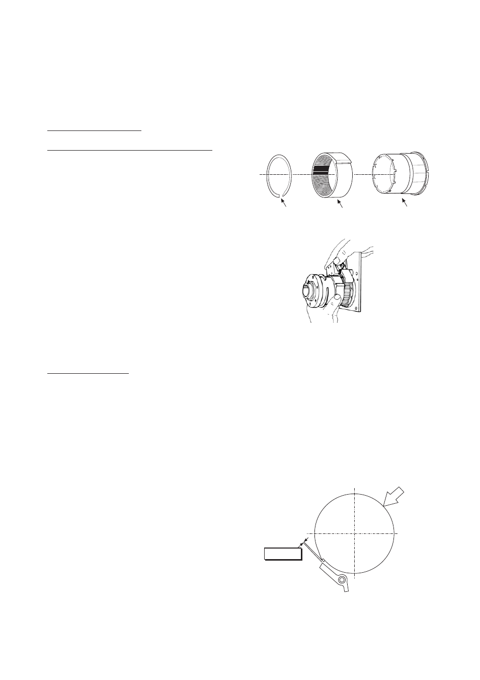
Align the cam face and actuator tip as shown in
Figure 1.
5.
Push the collar as indicated by the arrow in Figure
1 to take up the free collar play.
6.
Check to ensure that the plunger is properly
seated.
7.
Using a shim between the actuator tip and cam
face, set the collar actuator clearance between
0,25 and 0,76 mm by repositioning the solenoid
assembly.
8.
Tighten the solenoid adapter plate screws.
9.
De-energize the solenoid and repeat steps 2
through 5 if necessary.
10. If equipped with an actuator limit stop, re-
energize the coil and set the limit stop as follows:
DC Coils :
Set the limit stop so it just contacts the actuator.
AC Coils :
Set the actuator-limit stop clearance of 0,12 and
0,50 mm at the closest point.
3.2 ACTUATOR SETTING
0,25 - 0,76 mm
Figure 1