Warner Electric E320 User Manual
Page 3
Warner Electric Europe • +33 (0)2 41 21 24 24
P-2035-WE • 2/13 3
2.2
Precautions in use and safety measures
During maintenance, ensure that the machine’s
moving parts are stationary and that there is no
risk of accidental start-up. All intervention have to be
made by qualified personnel, owning this manual.
3 Installation
3.1
Transport / storage
Our clutches and brakes are supplied in packaging
guar anteeing a preservation period of 6 months with
land or air transport, or after transport by ship to
neighbouring conti nents (without crossing the tropics).
3.2
Handling
Avoid any impacts on the equipment so as not
to alter their performance.
Never carry the equipment by the electrical
supply cable.
3.3
Installing
E320 are delivered with bore / tolerance H7 and keyway/
tolerance P9 according to NFE22175 / DIN6885 /
ISO R773 / BS 4235. The mobile plate assembly (353)
is delivered with bore / tolerance H7. We recommand to
use tolerance h6 for shaft and g6 for the mobile toothed
ring assembly (352).
The pin should not generate any stress on the bearings.
In case of vibrations, it is strongly recommended to
insert a damping elastic slot between the anti-rotation
device and the anti-rotation slot and to fix the coil’s
cable the nearest of it to avoid whipping.
In the case where two co-axial shafts are
fitted, the recommended setover is 0,05 mm
maximum.
The angular misalignment should not be greater than
0,1 mm over a length of 100 mm. If this is the case,
use a VAR05 (flexible coupling).
3.3.1 Installing VAR00/VAR04/VAR10/VAR14
•
Center the mobile toothed ring assembly (352) or the
mobile plate (353) on the driven part, then fix it
with screws and lock them
•
After adjusting the driving key, mount inductor on
the shaft and fix it axially onto the shaft
It is important to tighten the locking screws from
mobile toothed assembly to the specified torque
(see table 2) or to the mobile plate (353) and secure
them with loctite 243 or an equivalent product.
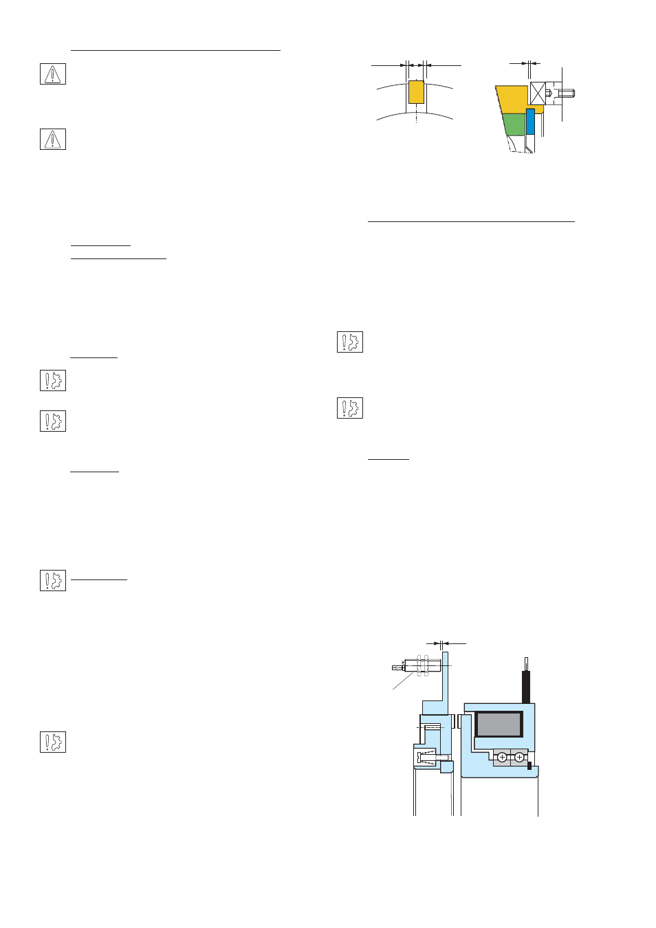
While assembling the driving and driven parts,
it is essential to note the value J (which is the
distance between tooth heads), see Table 1.
3.3.2 VAR504
Detection discs (aluminium or steel) compatible with
induc tive proximity sensor are provided with unit.
The position of the sensor should not obstruct the
travel of the toothed flange (352) (353).
We suggest to use the inductive sensor (615) provided
by our company, (see technical form).
MOUNTING EXAMPLE
1
0,25
0,25
Fig. 1
Sensor
Airgap
Any modification made to the brake without
the express authorisation of a representative
of Warner Electric, in the same way than any use out
of the contrac tual specifications accepted by “Warner
Electric”, will result in the warranty being invalidated
and Warner Electric will no longer be liable in any way
with regard to conformity.
Important: It is important to prevent inductor
(101) from rotating. It is the customers
responsibility to supply means to prevent inductor
rotating. i.e. retention pin in slot.Check gaps between
the inductor and the retention pin (see Figure 1) :
minimum 0,5 mm gap -1 mm gap at the slot bottom.