Warner Electric ERDD User Manual
Page 3
Warner Electric Europe • +33 (0)2 41 21 24 24
P-2062-WE • 2/13 3
Use the handling
holes provided for
any operation (See
Fig. 1, table 1).
Never transport
the unit by the
cable.
2.2
Precautions and safety measures
During the maintenance period make sure
that the moving parts of the machine are
stationary and that there is no risk of start-up.
All intervention have to be made by qualified
personnel, owning this manual.
It is imperative that the release screws (903) are
mounted before any operation is made to the
unit.
Any modification made to the brake without
the express authorisation of a representative of
Warner Electric, in the same way than any use
out of the contrac tual specifications accepted
by “Warner Electric”, will result in the warranty
being invalidated and Warner Electric will
no longer be liable in any way with regard to
conformity.
3
Installation
3.1
Transport / storage
These units are delivered in packaging that
guarantees a 6 months storage period whether
transported by land, by air, or by sea to any
destination excepting tropical countries. (For
tropical destinations please consult Warner
Electric technical services).
3.2
Handling
The unit is supplied pre-assembled except for
the hub.
Do not expose the unit to shocks whilst
handling as this may reduce performance.
3.2
Installation
To
mount the unit proceed as follows: according
to types, (see appendices 1 or 2):
Compress springs with release screws (903).
The moving armature (330) must be pulled
against the inductor (101).
Loosen the locking screws (909), the friction
plate (348), the friction disc(s) (312) and the
intermediate disc (320) or (321) for brakes with
dual discs.
Slide the hub (515) onto the shaft to be braked,
fit the driving key and secure it axially.
Keep the driving splines free of oil (i.e. friction
disc / hub). Otherwise this may reduce
performance.
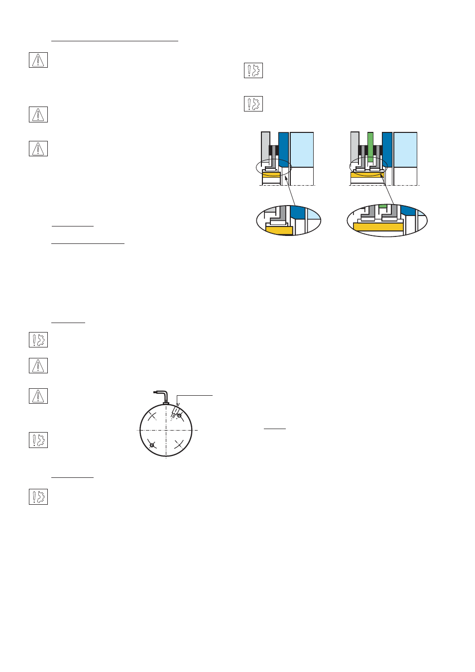
It is important to note the hub mounting
directions (See Fig. 2).
The hub is normally supplied with the following
norms : tolerances H7 for bore, P9 for keyways
(According to NF E 22-175/DIN 6885/BS 4235/ISO
R773).
Fit the friction plate (348) onto the mounting
surface. For single disc brakes from size 3200 and
for dual disc brakes from size 6400, the friction
plate is directly fixed on the mount with CHC
screws (not provided) and secure them with a
LOCTITE 270 product.
Now install the friction disc (312). If this is a dual
disc brake, then fit the intermediate disc (320) or
(321) and finally install the second friction disc
(according to size).
NOTE: The angle of the friction discs must be
facing the friction plate (see Fig. 2).
Slide the pre-campled moving armature (330) /
inductor (101) between the friction faces and fix
it with locking screws (909) and washers noting
carefully the tightening torque (see table 1 page 2).
Remove release screws (903). Energize the unit
(see chapter 5) and check if the friction disc
rotates freely.
Energise the brake a number of times whilst the
motor is static and check the nominal airgap value
(See table 1 page 2) near the faces of the friction
plate (348). If insufficient airgap, see chapter 4
(maintenance)
Fig. 1
Handling
screw
ERD
ERDD
Fig. 2