Warner Electric ERDD User Manual
Page 2
2 Warner Electric Europe • +33 (0)2 41 21 24 24
P-2062-WE • 2/13
We,
WARNER ELECTRIC EUROPE, 7, rue Champfleur, B.P. 20095, F-49182 St Barthélemy d’Anjou Cedex
declare that these brakes are made in our factory from St Barthélemy d’Anjou,
and hereafter designated :
ERD and ERDD
are exclusively designed for incorporation into a machine and to be assembled with other equipments to create a machine. The operation of the
product is submitted to the conformity of the complete equipment, following the provisions of the machinery directive 98/37/EC and if electric
to the EMC directive 89/336 /EEC. The conformity of the electric units to the Low Voltage directive 72/23 is supported by the full respect of the
following standards : NFC 79300 and VDE 05808/8.65.
Drawn up in St Barthélemy d’Anjou, July 2002
E. PRAT, General Managing Director
CONTENTS
1
Technical specifications
2
2
Precautions and restrictions on use
2
2.1
Restrictions on use
2
2.2
Precautions
3
and safety measures
3
Installation
3
3.1
Transport - storage
3
3.2
Handling
3
3.3
Installing
3
4
Maintenance
4
4.1
Adjusting the airgap
4
1
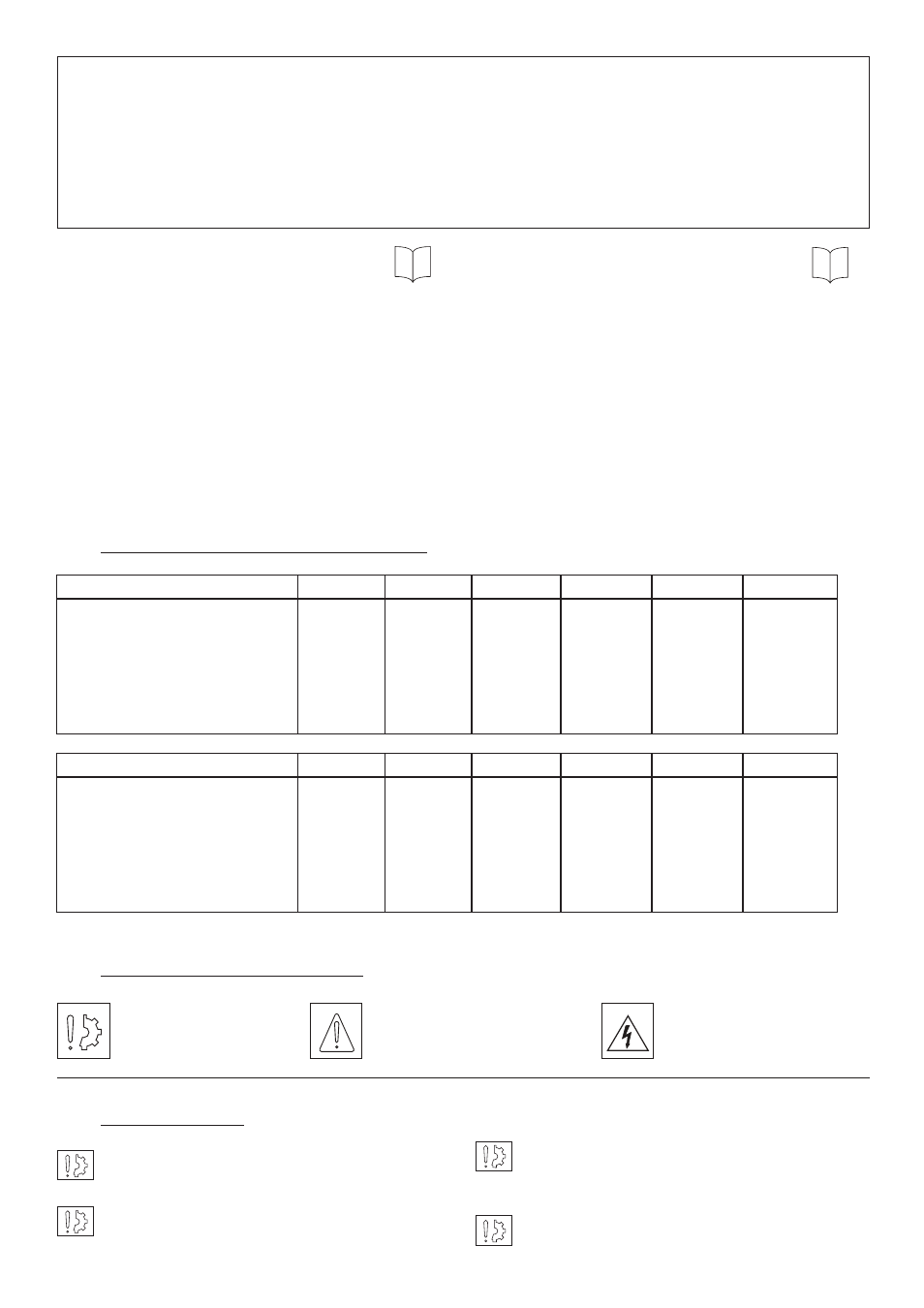
Technical specifications (VAR00 and VAR03)
ERD Size
500
800
1600
3200
6400
12800
Nominal airgap
mm
Airgap tolerance
mm
Pull-in airgap max.
mm
Tightening torque screw 909 Nm
Number of screws (Rep. 903)
-
Handling Screws
-
Allowable wear max*
mm
0,4
± 0,005
1
48(±10%)
2xM10x80
M8
4
0,6
+0,05/-0,1
1,5
48(
±10%)
4xM12x90
M12
4
0,6
+0,05/-0,1
1,5
110(
±10%)
3xM16x110
M12
6,5
1
±0,1
2
150(±10%)
8xM20x120
M16
9
1,3
±0,15
2,5
260(±10%)
8xM20x140
M16
10
1,5
±0,15
3
380(±10%)
8XM20X180
M20
14,7
4.2
Adjusting the detector
4
5
Electrical connection
4
5.1
Important recommendations
4
5.2
Power supply
4
6
Options
5
6.1
Torque adjustment
5
6.2
Detection kit
5
7
Appendices
6-7
7. 1
Appendix 1 (ERD 500 to 1600 and
6
ERDD 1000 to 3200)
7. 2
Appendix 2 (ERD 3200 to 12800 and
7
ERDD
6400 to 25600)
ERDD Size
1000
1600
3200
6400
12800
25600
Nominal airgap
mm
Airgap tolerance
mm
Pull-in airgap max.
mm
Tightening torque screw 909 Nm
Number of screws (Rep. 903)
-
Handling Screws
-
Allowable wear max*
mm
0,5
± 0,05
1
48(±10%)
2xM10x80
M8
9
0,7
+0,05/-0,1
1,5
48(
±10%)
4xM12x90
M12
10,5
0,7
+0,05/-0,1
1,5
110(
±10%)
3xM16x110
M12
13,5
1,3
±0,1
2
150(±10%)
8xM20x120
M16
16,5
1,7
±0,15
2,5
260(±10%)
8xM20x140
M16
15
1,9
±0,15
3
380(±10%)
8XM20X180
M20
15,5
Table 1
*See paragraphs 4-2 and 4-3
2
Precautions and restrictions on use
2.1
Restrictions on use
These units are designed for dry operation. The
brake must be free from oil and grease.
Exceeding the maximum rotation speed listed in
the catalogue will invalidate the guarantee.
ERD 500, ERD 800 and ERD 1600 can be hori-
zontally or vertically mounted, all other units can
only be mounted horizontally.
Ambient temperature for these units is
max 40° C (insulation class of 155°C).
Symbol designating
an action that might
damage the brake
Symbol designating an
action that might be
dan gerous to human safety
Symbol designating an
elec trical action that might be
dangerous to human safety